Check out the project on GitHub.
A while back, I wrote about how I use javacard chips for all kind of systems. One of the authentication protocols these chips support (given a compatible applet is installed) is FIDO2.
I won’t go into what FIDO is or why it is such a big deal, you can find plenty of resources on that topic. Even though FIDO2 is quite a few years old and has broad industry support, most devices only support the USB HID transport protocol, not the PC/SC smartcard protocol which the NFC tokens use. Some operating systems like Windows provide an abstracted API which covers both protocols, but on MacOS and Linux you are out of luck.
So, what to do? Patch all affected clients and implement a second interface protocol? Sounds like a lot of (redundant) work, and is not an option for closed-source software. Instead, I wrote a piece of code which translates a PC/SC NFC FIDO2 interface into a USB HID one, by creating a virtual USB interface using the Linux kernel USB gadget functionality. See https://github.com/StarGate01/CTAP-bridge for this implementation.
This works fine on a system which is based on Linux and allows modification of the kernel, and also grants you root access. Not something which you have on an enterprise machine. In addition, MaxOS does not support this kind of kernel interface at all. So instead, I set out to build a hardware solution which would work with any USB-accepting system.
Raspberry Pi Zero and MAX3421E
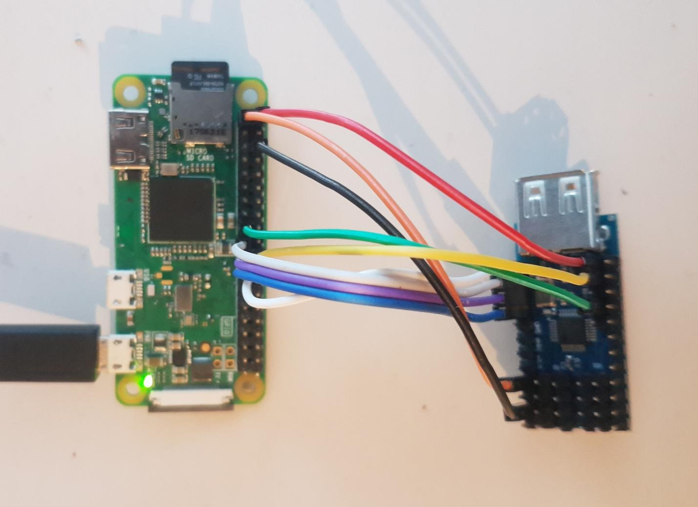
For testing, I opted to use a Raspberry Pi Zero W 1.1, because that was the one I found in a drawer and it is also a cheap and lightweight platform. Unfortunately, this board (like all Raspberry Pis) has only one USB host controller. Since we need to do USB proxying, we need two controllers – one to interface the PC/SC NFC reader, and one to emulate a FIDO2 USB HID token to the PC. Luckily, there is a inexpensive chips called MAX3421E, which provides a USB 2.0 host interface via a SPI connection.
Hardware Connection
I bought a cheap module from Amazon, which is documented here. I cut the V_BUS trace as shown in the image, in order to separately supply the 5V USB power. See also this discussion.
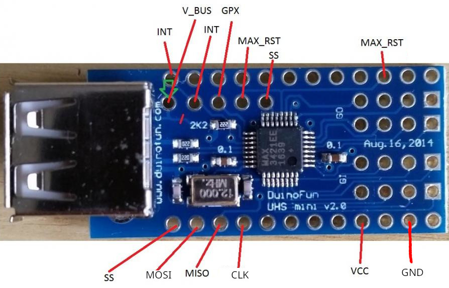
| Raspberry Pi Zero Pin | MAX3421E Pin |
| 5V Power | V_BUS |
| P22 (GPIO 25) | INT |
| Ground | GND |
| 3.3V Power | MAX_RST |
| P24 (GPIO 8, SPI0 CE0) | SS |
| P23 (GPIO 11, SPI SCLK) | CLK |
| P21 (GPIO 9, SPI MISO) | MISO |
| P19 (GPIO 10, SPI MOSI) | MOSI |
| 3.3V Power | VCC |
Compiling the MAX3421-HCD Kernel Driver
The MAX3421E kernel driver is not included by default in the Raspberry Pi OS distribution, so it has to be built and installed manually.
Install dependencies, update to current kernel, and download current kernel source:
$ sudo nano /etc/sources.list
# Uncomment specified line to enable source download and save
$ sudo nano /etc/sources.list.d/raspi.list
# Uncomment specified line to enable source download and save
$ sudo apt-get update
$ sudo apt-get upgrade
$ sudo apt-get install git bc bison flex libproc-processtable-perl build-essential wget libssl-dev make libncurses-dev raspberrypi-kernel-headers
$ sudo reboot
$ uname -a
# Note the kernel version (e.g. 6.1.58-1+rpt2)
$ sudo apt list -a linux-image-rpi-v6
# Ensure kernel versions match, adjust versions if needed
$ sudo apt-get source linux-image-rpi-v6/stable
$ sudo chown -R pi:pi linux-6.1.58
Compile and install kernel module:
$ cd linux-6.1.58
$ cp /usr/src/linux-headers-$(uname -r)/Module.symvers .
$ sudo modprobe configs
$ zcat /proc/config.gz > .config
$ make oldconfig
$ make menuconfig
# Enable (M): "Device Drivers" -> "USB support" -> "MAX3421 HCD (USB-over-SPI) support"
# Save and Exit
$ make modules_prepare
$ make -C . M=drivers/usb/host
$ sudo mkdir -p /lib/modules/$(uname -r)/kernel/drivers/usb/host
$ sudo cp drivers/usb/host/max3421-hcd.ko /lib/modules/$(uname -r)/kernel/drivers/usb/host
$ sudo chown root:root /lib/modules/$(uname -r)/kernel/drivers/usb/host/max3421-hcd.ko
$ sudo depmod
$ sudo modprobe max3421-hcd
$ lsmod | grep max3421
$ sudo rmmod max3421_hcd
Automatic Driver Loading and Device Tree Configuration
In order to properly configure the driver, a device tree configuration has to be provided. This tells the driver which hardware pins to use, which frequency to run the SPI interface on, and so on. I found an example in this repository and the Linux source, which I adapted.
/dts-v1/;
/plugin/;

/ {
    compatible = "brcm,bcm2835";
    /* Disable spidev for spi0.0 - release resource */
    fragment@0 {
        target = <&spi0>;
        __overlay__ {
            status = "okay";
            spidev@0{
                status = "disabled";
            };
        };
    };

    /* Set pins used (IRQ) */
    fragment@1 {
        target = <&gpio>;
        __overlay__ {
            max3421_pins: max3421_pins {
                brcm,pins = <25>;       //GPIO25
                brcm,function = <0>;    //Input
            };
        };
    };

    /* Create the MAX3421 node */
    fragment@2 {
        target = <&spi0>;
        __overlay__ {
            //avoid dtc warning
            #address-cells = <1>;
            #size-cells = <0>;
            max3421: max3421@0 {
                reg = <0>;  //CS 0
                spi-max-frequency = <20000000>;
                compatible = "maxim,max3421";
                pinctrl-names = "default";
                pinctrl-0 = <&max3421_pins>;
                interrupt-parent = <&gpio>;
                interrupts = <25 0x2>;      //GPIO25, high-to-low
                maxim,vbus-en-pin = <1 1>;  //MAX GPOUT1, active high
            };
        };
    };
};
Now, to compile and install this device tree overlay:
$ nano max3421-hcd-overlay.dts
$ dtc -@ -I dts -O dtb -o ./max3421-hcd.dtbo ./max3421-hcd-overlay.dts
$ sudo dtoverlay ./max3421-hcd.dtbo
$ dtoverlay -l
If all went well, the module should be loaded automatically by the overlay, and dmesg should report something like this:
max3421-hcd spi0.0: property 'maxim,vbus-en-pin' value is <1 1>
max3421-hcd spi0.0: MAX3421 USB Host-Controller Driver
max3421-hcd spi0.0: new USB bus registered, assigned bus number 2
usb usb2: New USB device found, idVendor=1d6b, idProduct=0002, bcdDevice= 6.01
usb usb2: New USB device strings: Mfr=3, Product=2, SerialNumber=1
usb usb2: Product: MAX3421 USB Host-Controller Driver
usb usb2: Manufacturer: Linux 6.1.61+ max3421
usb usb2: SerialNumber: spi0.0
max3421-hcd spi0.0: rev 0x13, SPI clk 20000000Hz, bpw 8, irq 160
hub 2-0:1.0: USB hub found
hub 2-0:1.0: 1 port detected
To persist the overlay into the firmware:
$ sudo cp ./max3421-hcd.dtbo /boot/overlays/
$ sudo nano /boot/config.txt
# Insert "dtoverlay=max3421-hcd" and save
Installing the CTAP Bridge
Next, the actual FIDO2 protrocol translator is installed. I wrote it a while back, for details see its README file: https://github.com/StarGate01/CTAP-bridge .
$ sudo nano /boot/config.txt
# Insert "dtoverlay=dwc2"
# Comment out "otg_mode=1" and save
$ sudo nano /etc/modules
# Insert "libcomposite" and save
$ sudo reboot
$ sudo apt-get install python3-full python3-pip swig pcsc-tools pcscd libpcsclite-dev
$ sudo systemctl enable pcscd
$ sudo systemctl start pcscd
$ git clone https://github.com/StarGate01/CTAP-bridge
$ cd CTAP-bridge
$ python -m venv myenv
$ source myenv/bin/activate
$ pip install -r requirements.txt
$ deactivate
$ sudo nano /etc/udev/rules.d/50-ctaphid.rules
# Insert the udev rules from the repository README and save
$ sudo udevadm control --reload-rules
$ sudo myenv/bin/python bridge.py
# CTRL-C eventually
Create a service file for the bridge via “nano ~/ctaphid.service“:
[Unit]
Description=CTAPHID bridge

[Service]
WorkingDirectory=/home/pi/CTAP-bridge
ExecStart=/home/pi/CTAP-bridge/myenv/bin/python ./bridge.py

[Install]
WantedBy=multi-user.target
Install the service:
$ sudo cp -f ctaphid.service /etc/systemd/system
$ sudo systemctl daemon-reload
$ sudo systemctl enable ctaphid.service
$ sudo systemctl start ctaphid.service
$ sudo systemctl status ctaphid.service
If you plug in the Raspberry Pi zero to another PC using the “data” Micro-USB port of the PI, it should be recognized as a “ID 1209:000c Generic pid.codes Test PID” and act as a FIDO2 USB token. I found that the power consumption stays at around 200 mA, even with with a PC/SC reader attached. Powering the Raspberry via a normal USB port should be possible.
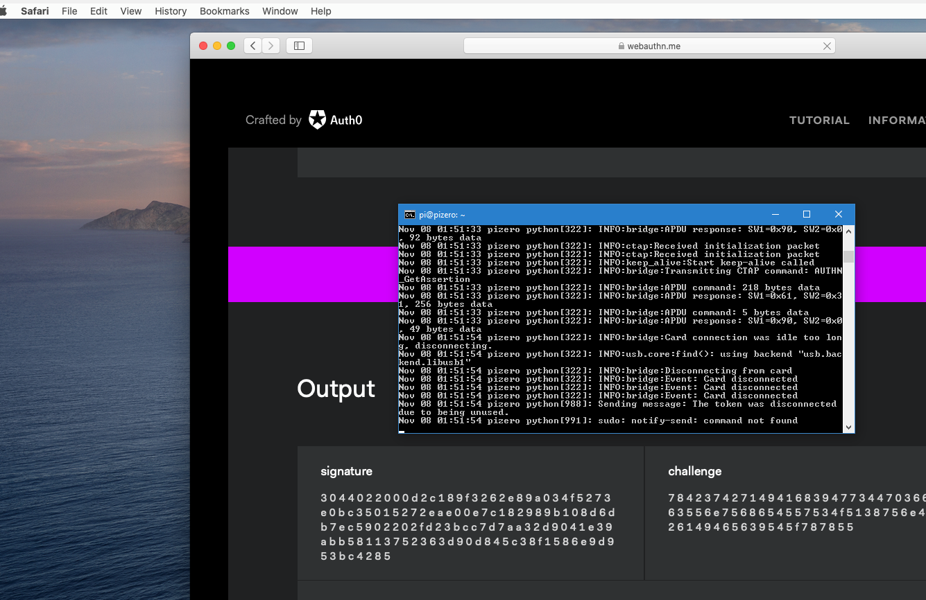
Conclusion
Now I can use NFC FIDO tokens, even on mac OS:
Thanks To / Sources
- https://github.com/stephaneAG/RPi/blob/master/max3421_spiUsbHost_working.md
- https://forum.pjrc.com/threads/43357-Teensy-with-mini-USB-host-shield-(chineese)
- https://github.com/RPi-Distro/rpi-source
- https://github.com/raspberrypi/linux/blob/rpi-6.1.y/Documentation/devicetree/bindings/usb/maxim%2Cmax3421.txt