Check out the project on GitHub.
After prototyping the MAX3421E USB host chip with the Raspberry Pi Zero in the previous blog entry to this series, I decided to design a custom PCB for this task.
Transparency Disclaimer: This project has been in part sponsored by the PCB manufacturing company PCBWay.
Circuit Design
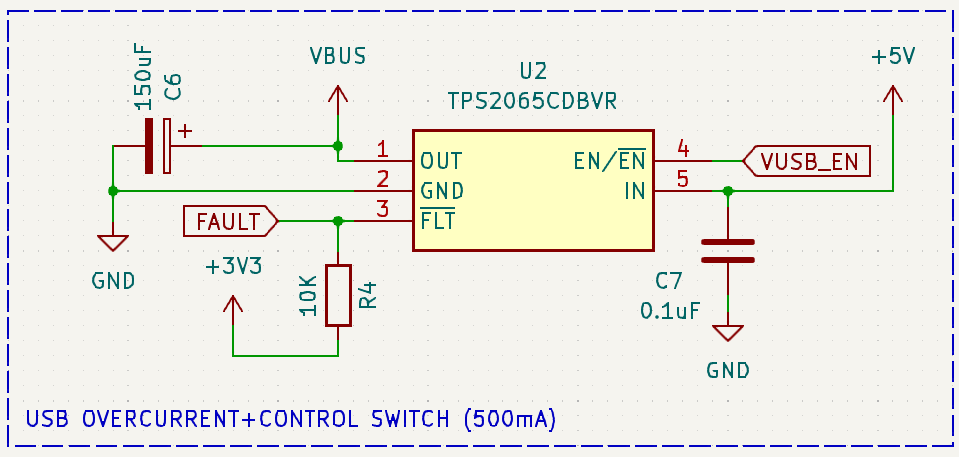
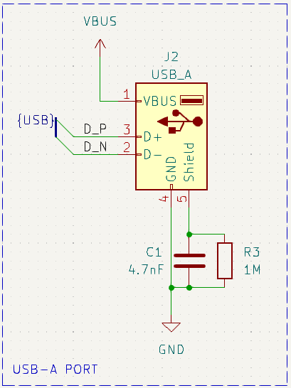
I used the public schematics of the Mini USB Host Shield 2.0 board I used previously as a starting point. In addition I referenced the application notes of the MAX3421E data sheet, which recommends a overcurrent protection switch:
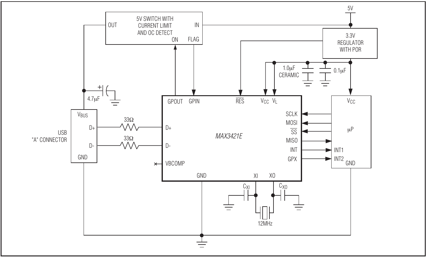
As shown in the diagram, the GPOUT pin 0 is used to toggle the current limiting VUSB switch. This is implemented in the Linux USB driver as well. GPX is used to notify the Raspberry if an overcurrent event occurs (via GPIN pin 0), but the driver currently does not handle this event.
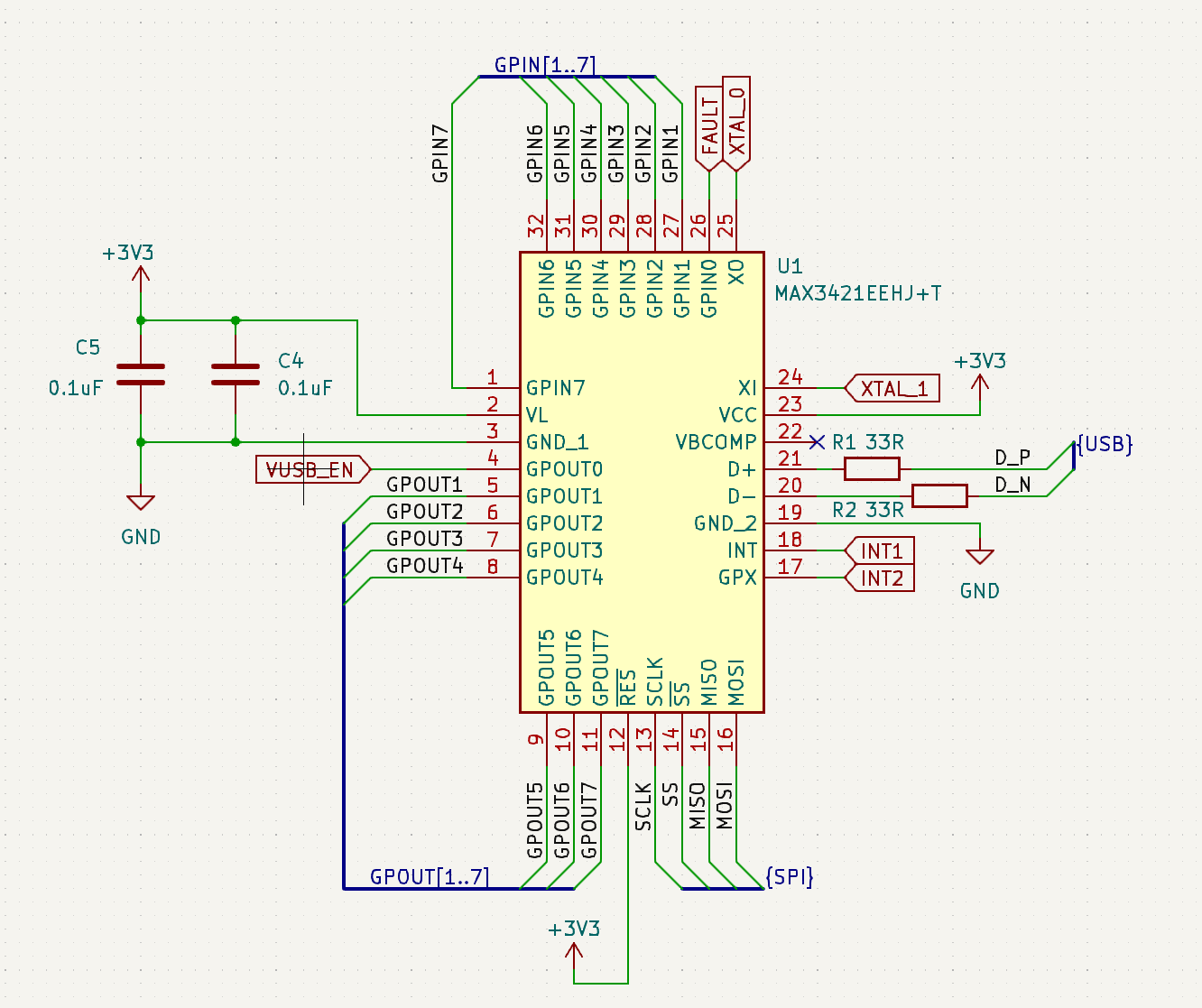
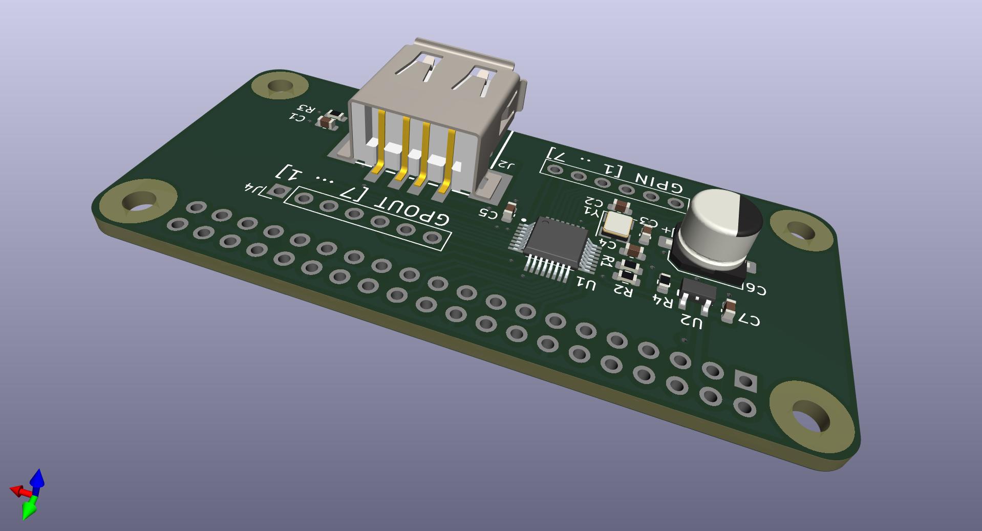
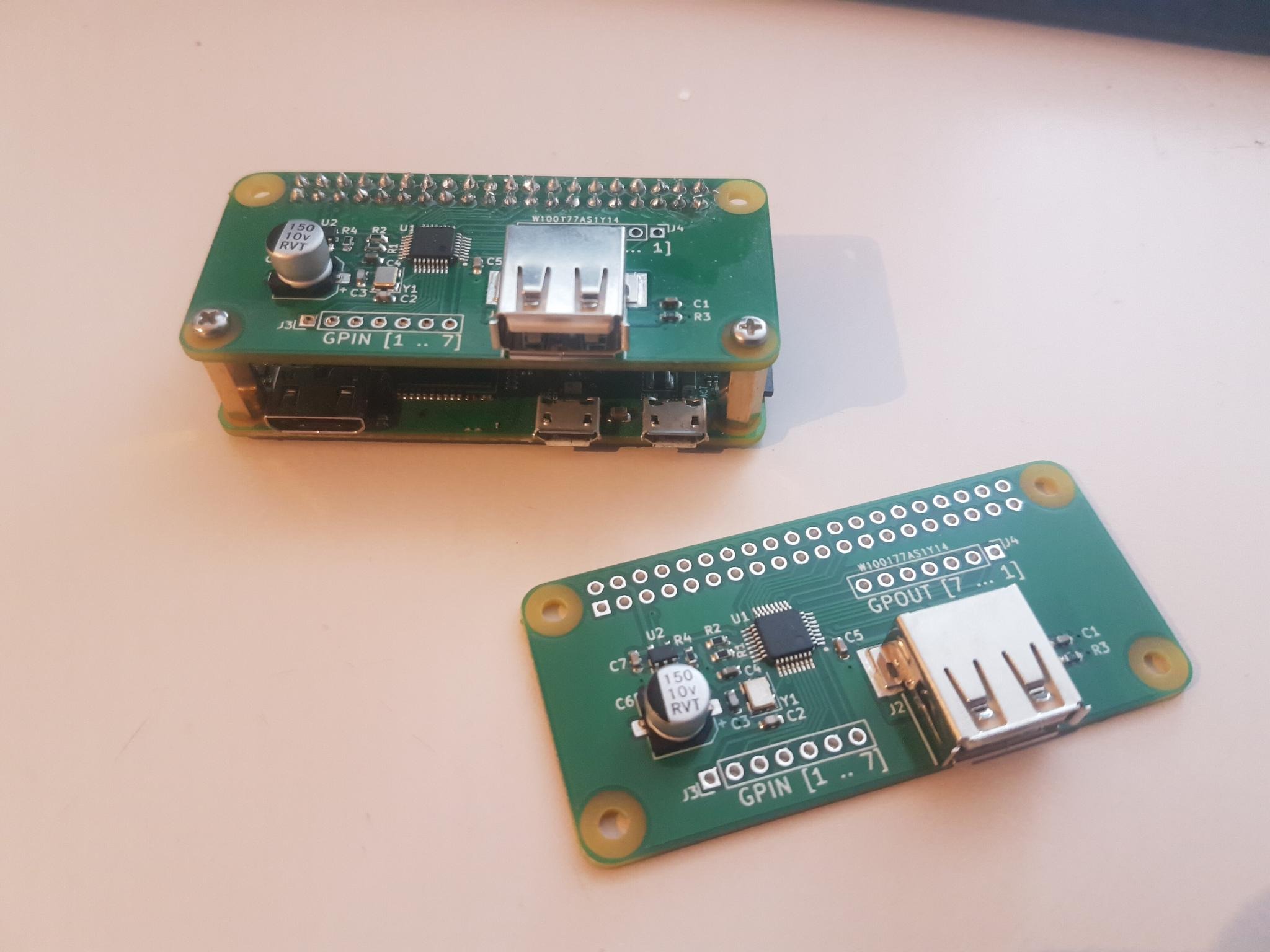
I also made sure to interface with the Raspberry Pi Zero GPIO header directly, in order to be able to stack the PCB directly on top of the Raspberry Pi Zero. You can find the final schematics in the KiCAD project for this design. The printed circuit board was designed to fit exactly on the Raspberry Pi Zero in terms of size and mounting holes.
Production
The PCBs were manufactured and assembled by PCBWay, they also handled component sourcing for me. As expected, the PCBs came out great and worked out of the box.
Alternatives
This project is meant as a retrofitting solution for Raspberry Pi Zeros, which do not have a second USB interface. If you do not own a Raspberry Pi Zero but need a new single board computer with two USB interfaces, I recommend buying an Orange Pi Zero 2W instead. That SBC has an Allwinner chip with two USB interfaces, which means it can do USB proxying without any additional hardware.