The XBOX 360 controllers are objectively the best controllers. And the wireless ones are nice because I don’t need to run wires for couch gaming. Even though they are becoming harder to find and I usually buy them used on Ebay, I care a lot for them. But what I don’t care for, are the included battery holders. They need a dedicated charging station (or a lot of fresh alkaline batteries), and the cell technology is also aging over the years. So I set out to upgrade my controllers to modern day LiPo batteries and USB-C charging.
Luckily, the controller has a very tolerant internal voltage regulator which can handle the 3.9 – 4.7 volts of the LiPo battery with no issues.
Some other parts I already had around the workshop:
Soldering equipment
3D-Printer
Dremel with small endmills and drills
Kapton tape
Wire
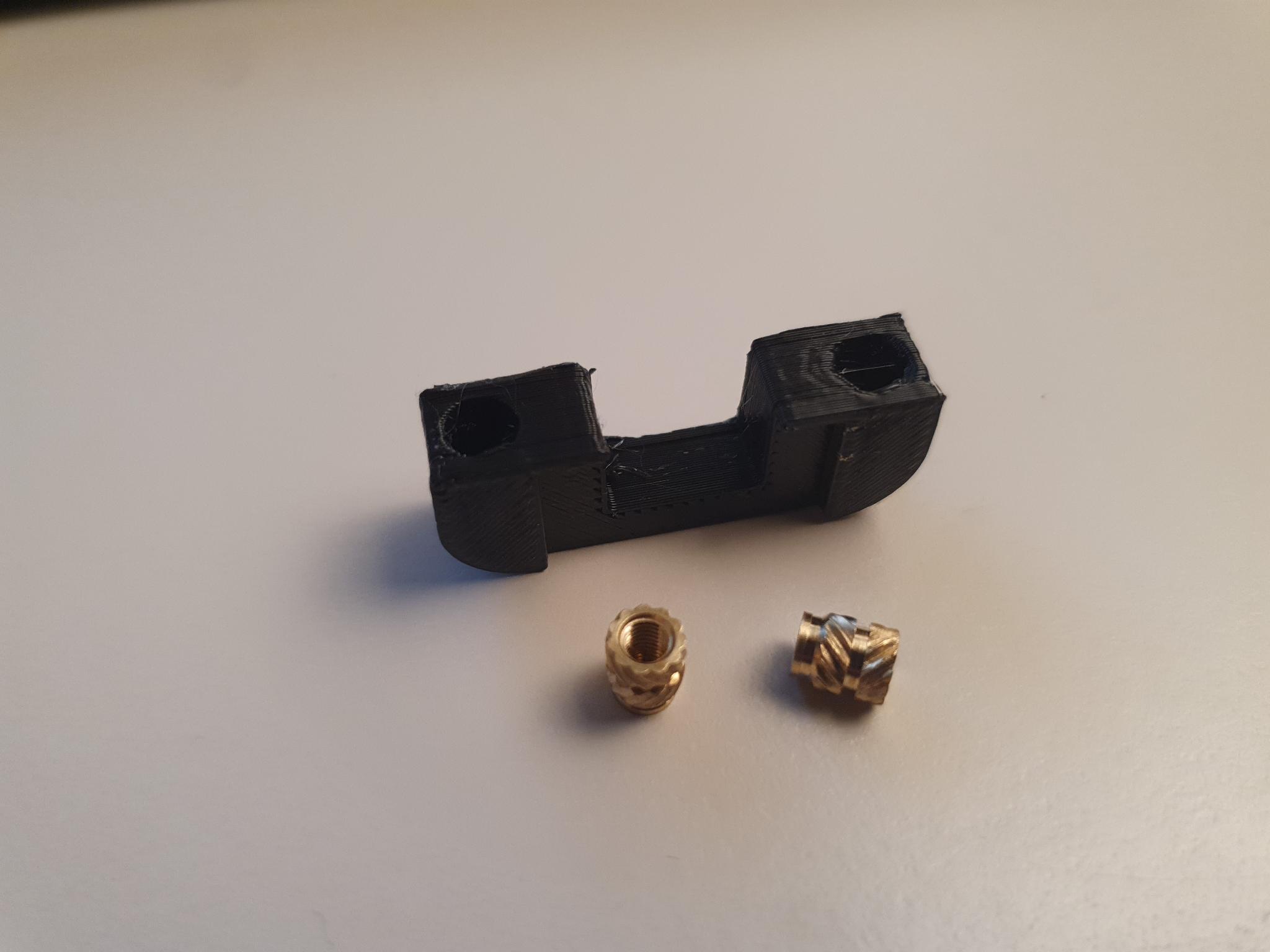
Heatset M3 x 6 x 5 inserts
M3 x 10 hex bolts
Strong plastic glue / Epoxy
Screwdrivers
Sandpaper
Battery Shell
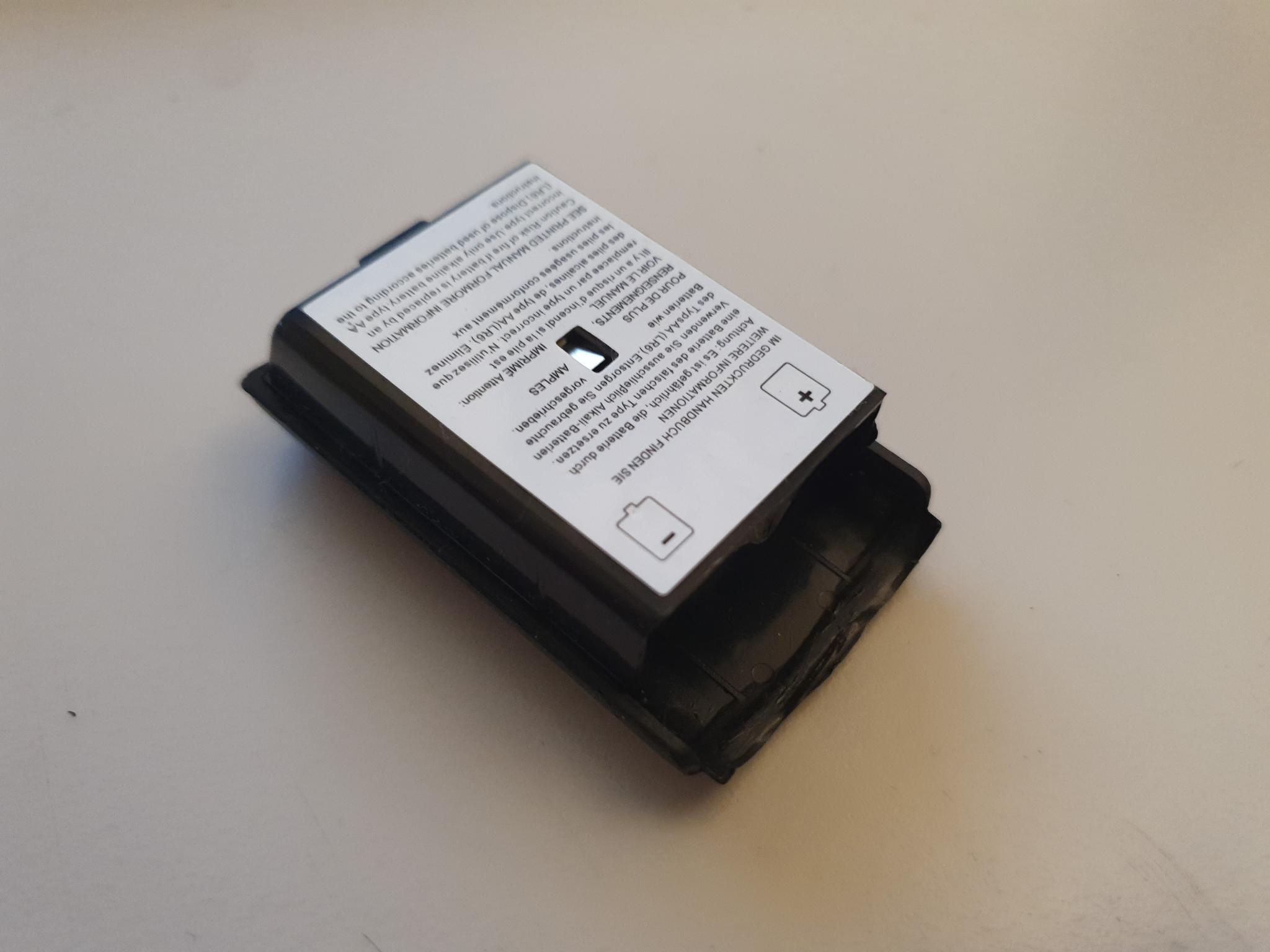
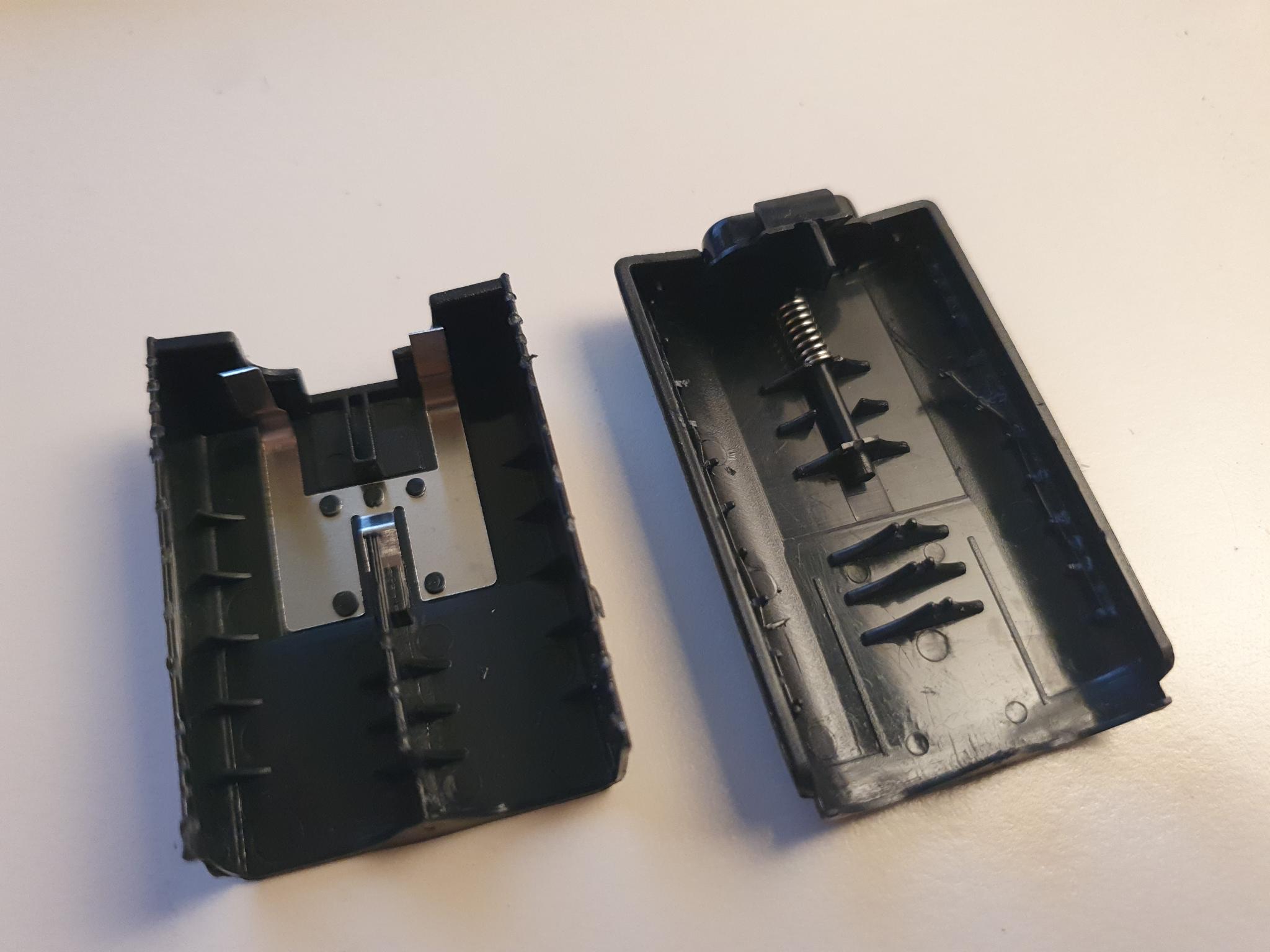
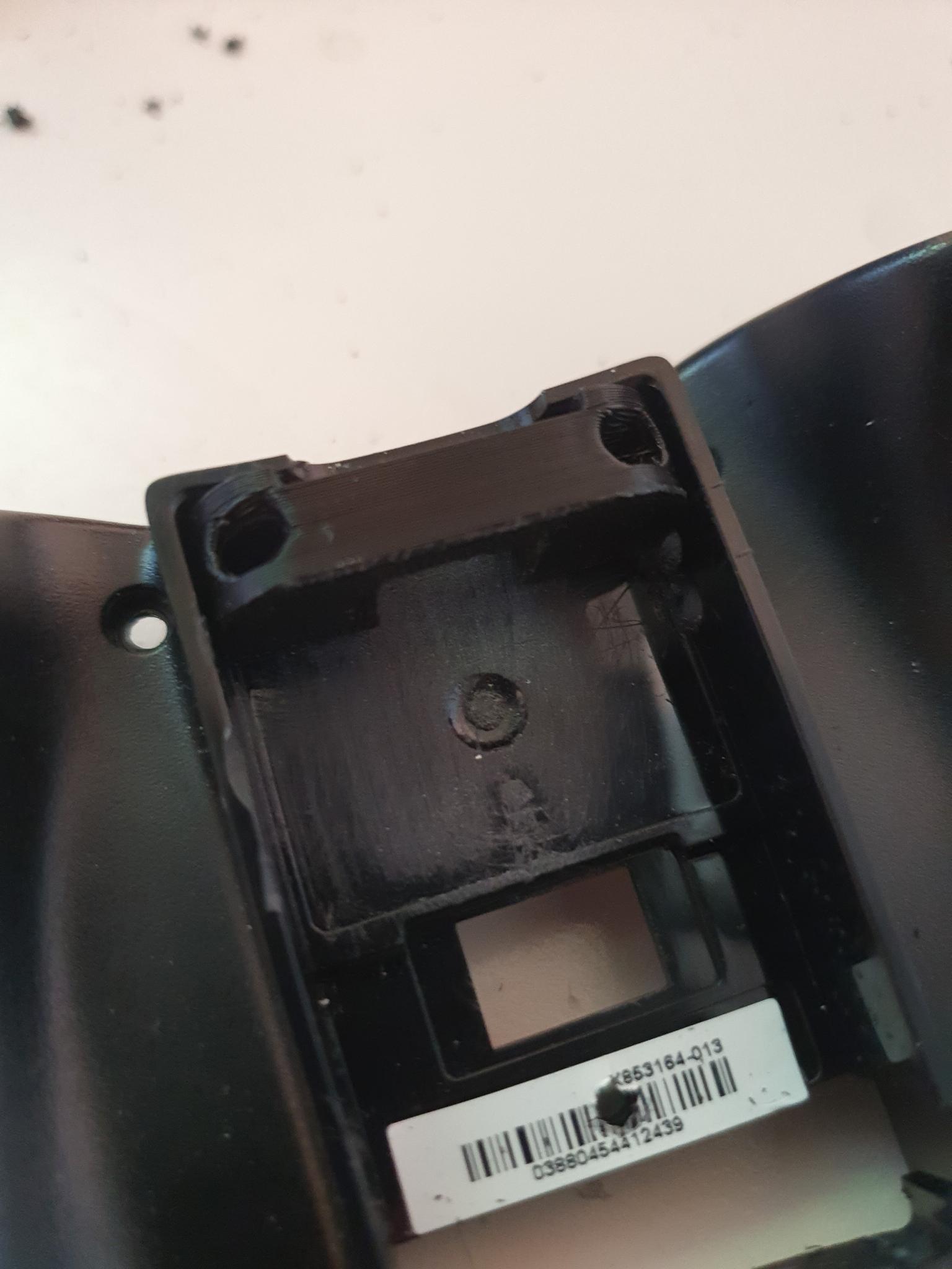
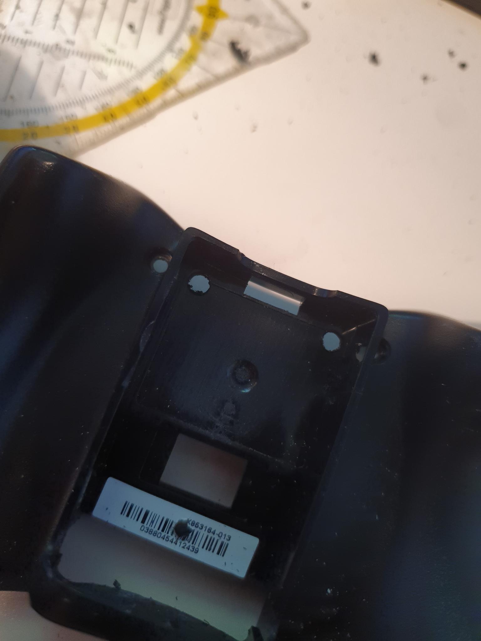
First, I modified the plastic battery holders to fit the new batteries.
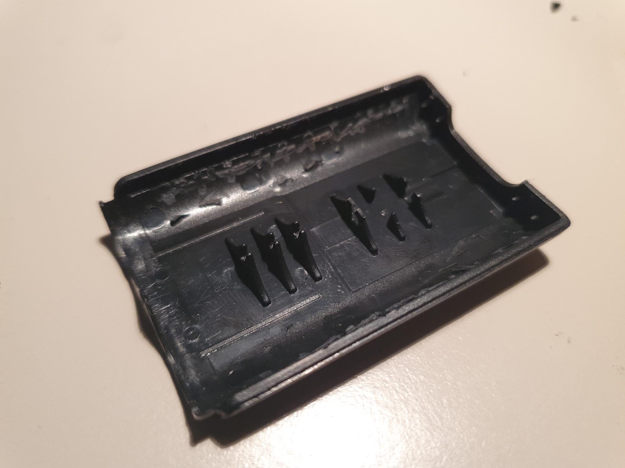
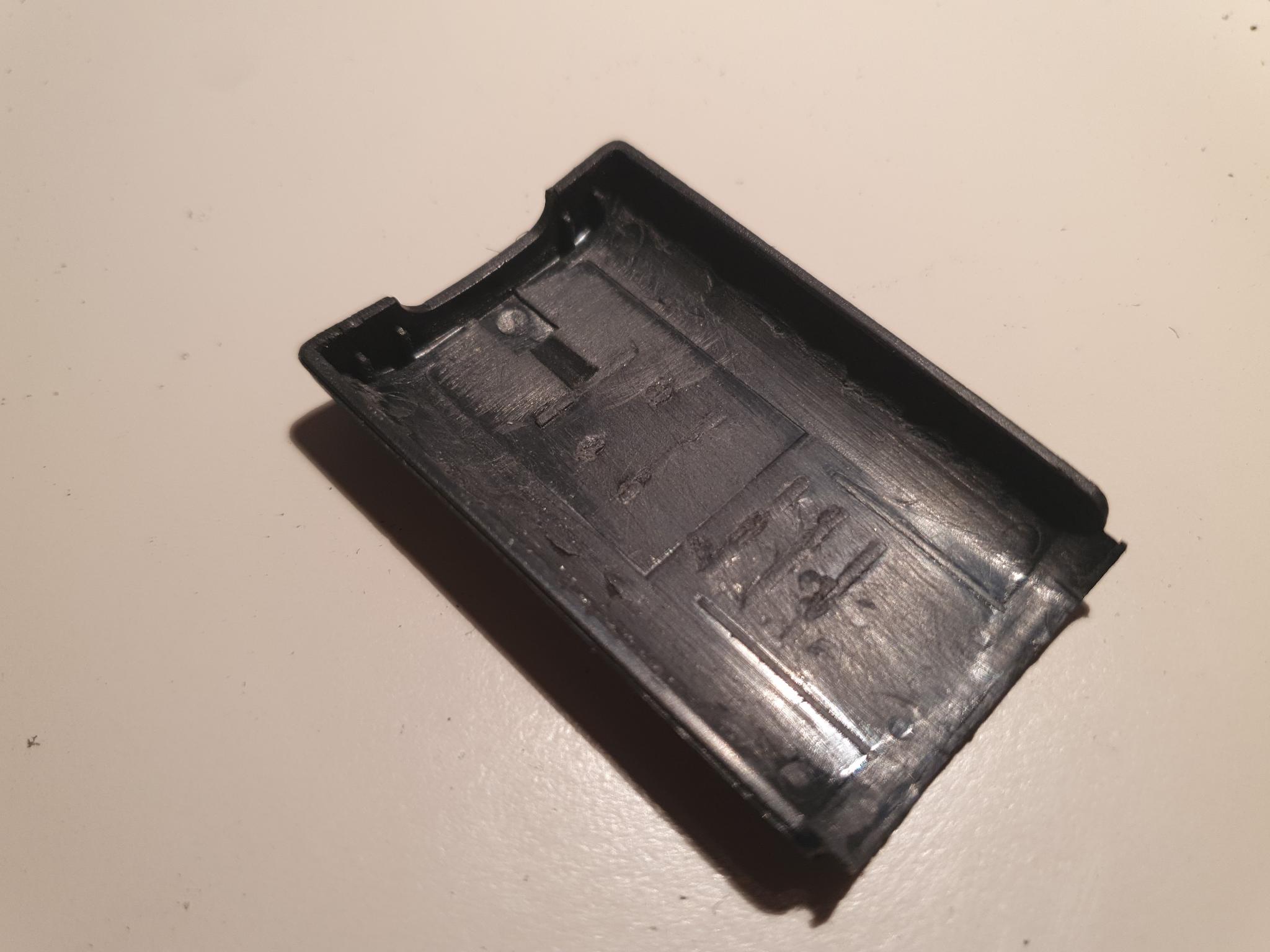
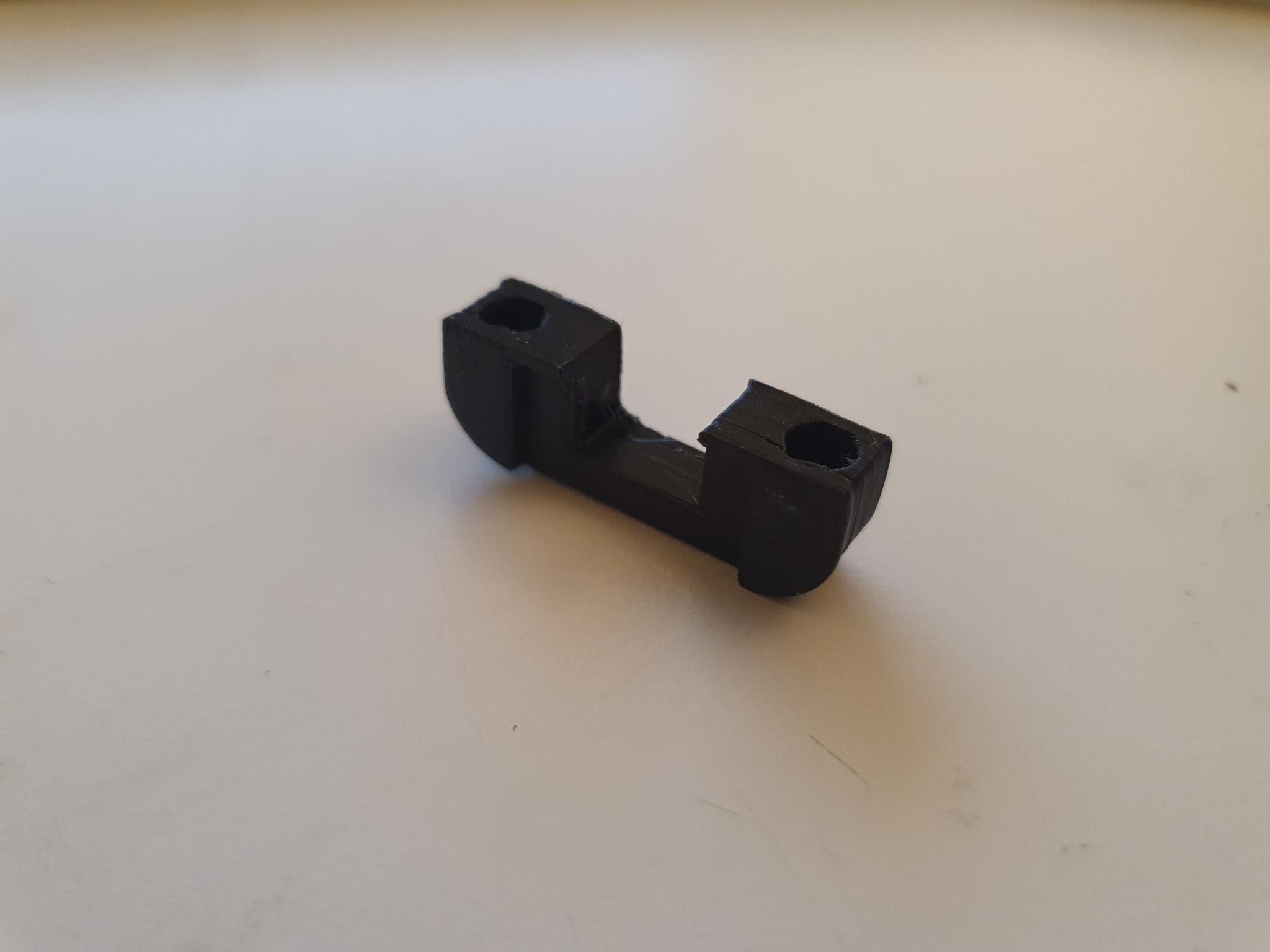
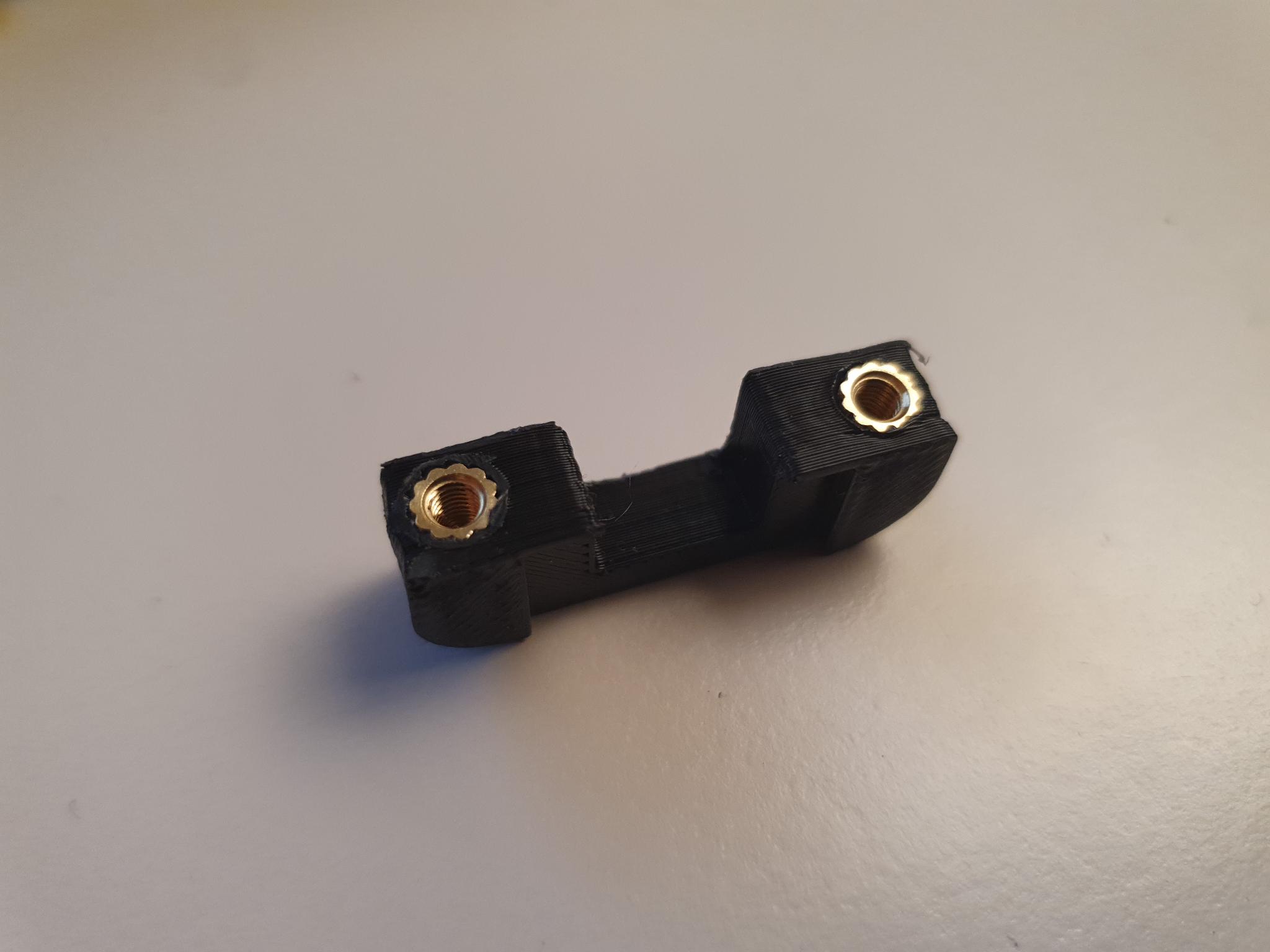
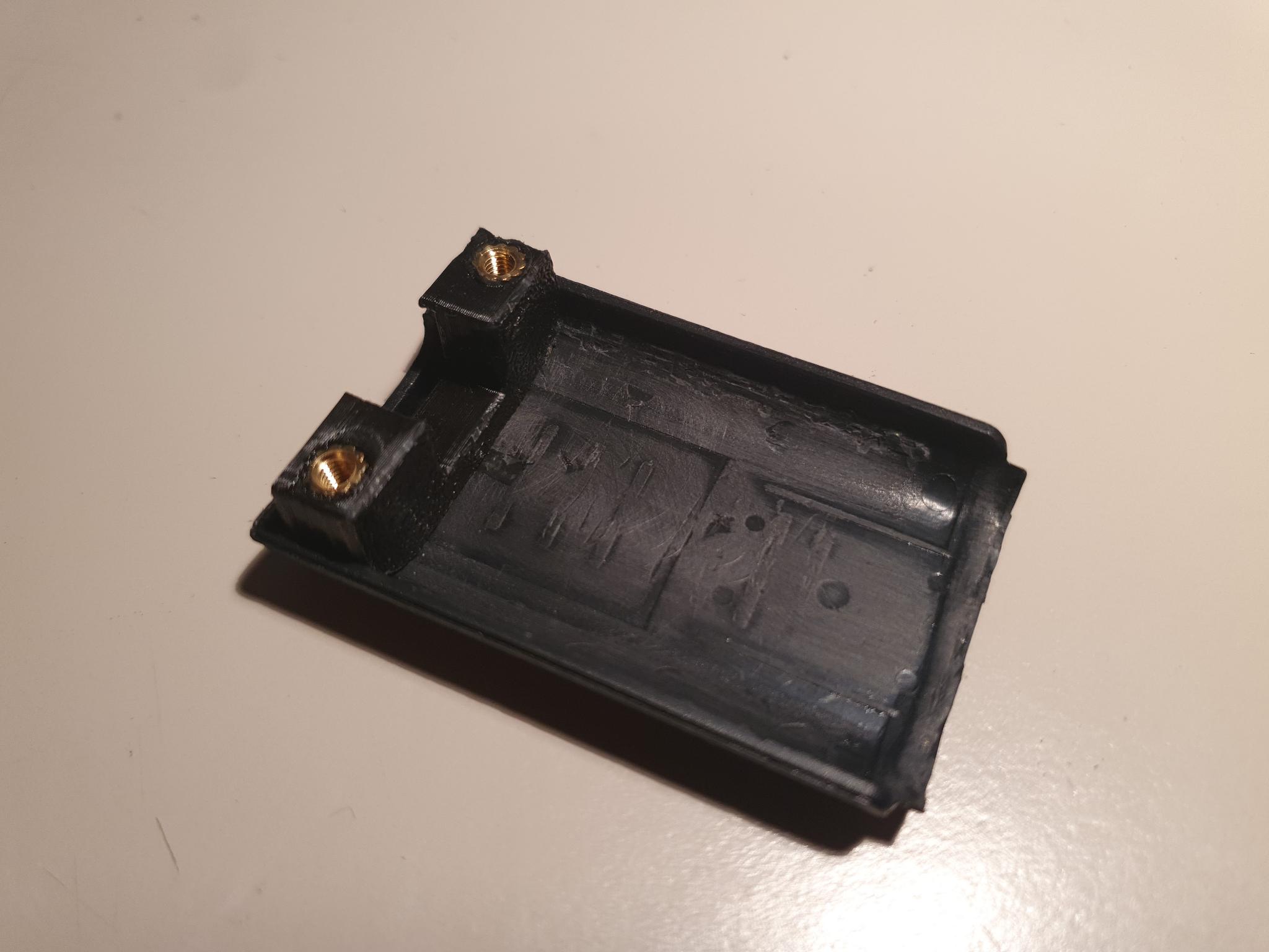
Plastic battery pack before modification.Plastic battery pack forced open into its two shell parts. Use e.g. a sturdy knife to pry these two parts apart and break the small ultrasonic plastic welds along the long sides. The side with the metal parts can be discarded, only the base is needed.The retention button mechanism is removed. The button is kept, it will be needed later. But these plastic rib structures in the shell need to go. Use a scalpel or a dremel to remove them, both on the inner sides as well as on the floor. On the bottom side there is also a small rim which needs to be cut away.The modified shell after a light sanding. It is important to rough up the surface to ensure the glue later properly bonds.This part is 3D-printed in PLA.Two M3 x 6 x 5 heatset inserts are prepared to be pressed into the holes using a soldering iron.The 3D printed part with the two heatset inserts fitted. The top surfaces have to be somewhat aligned and the holes need to be straight.The 3D-printed part fits into the shell like this.
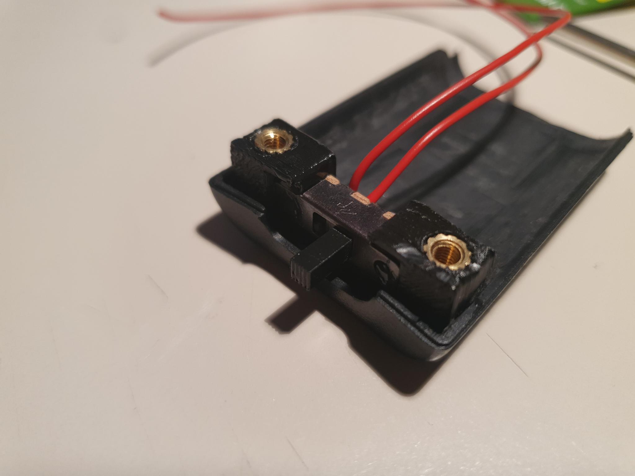
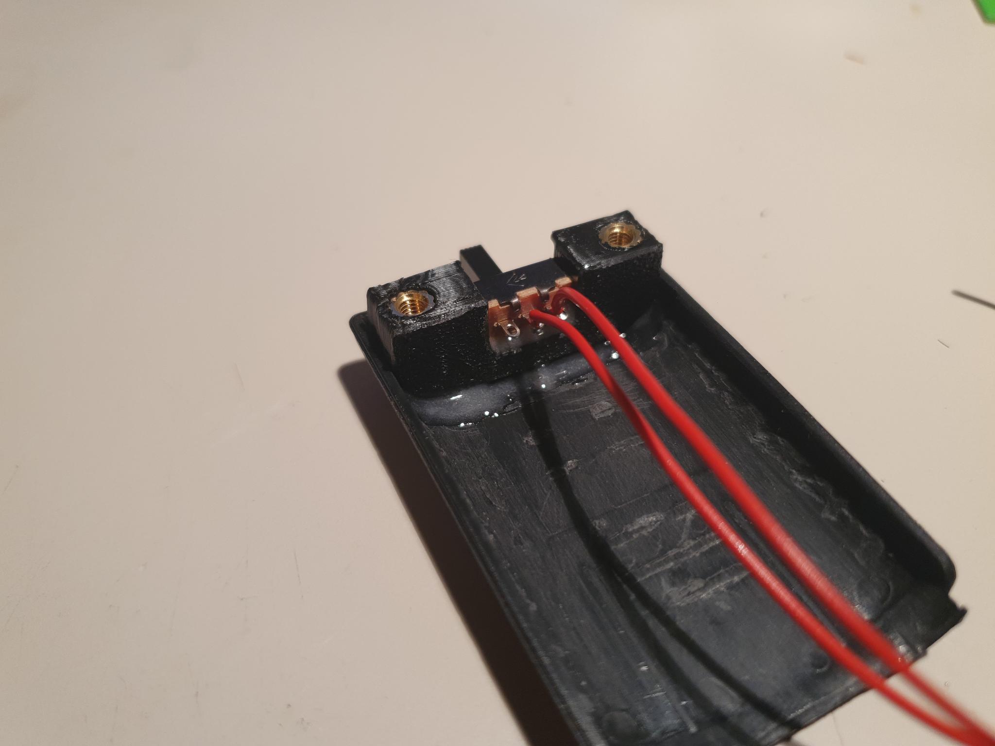
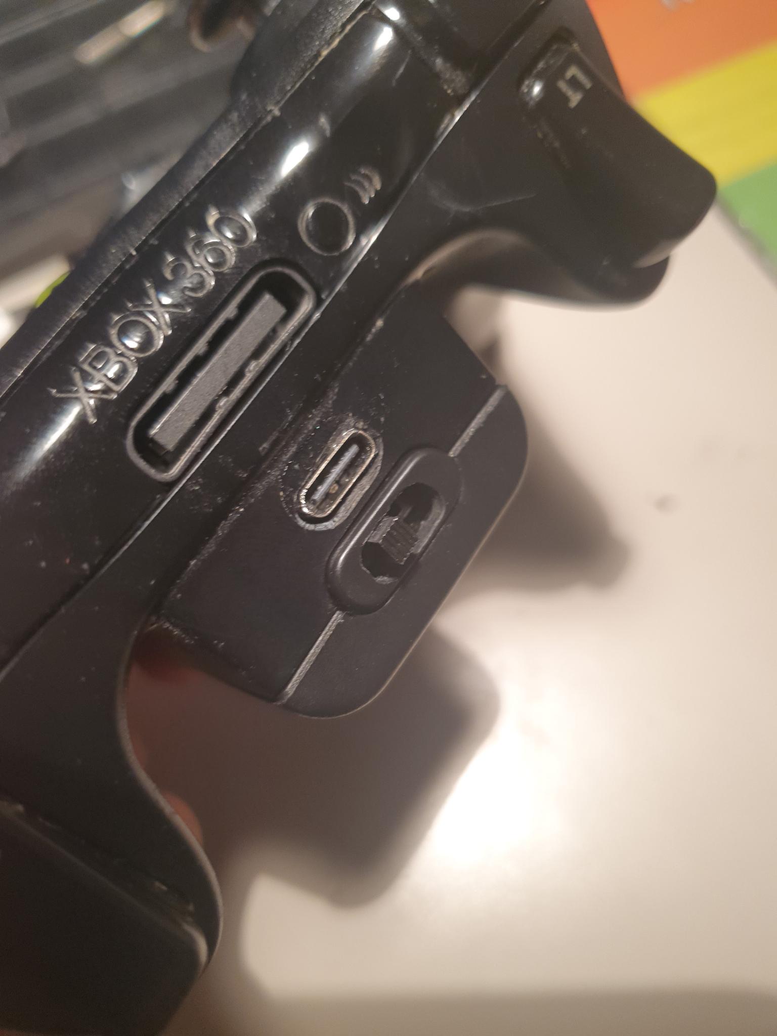
Power Switch
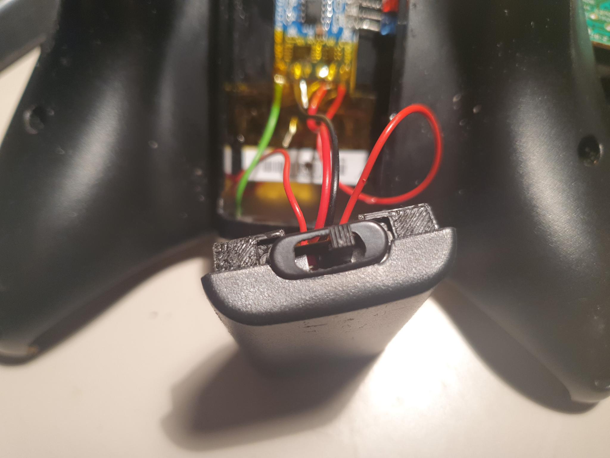
In my opinion, the wireless controllers always missed a proper power switch, so I added one.
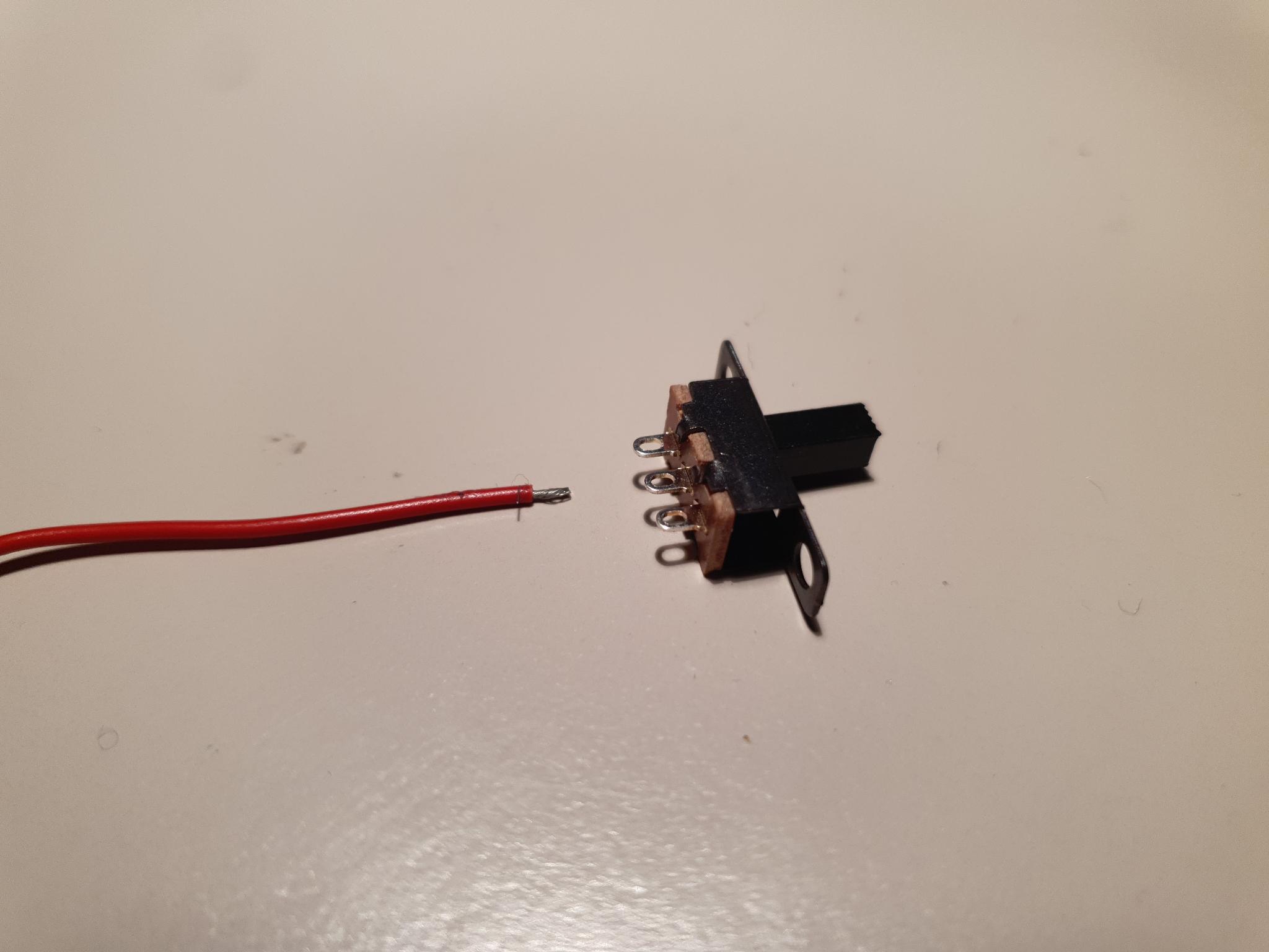
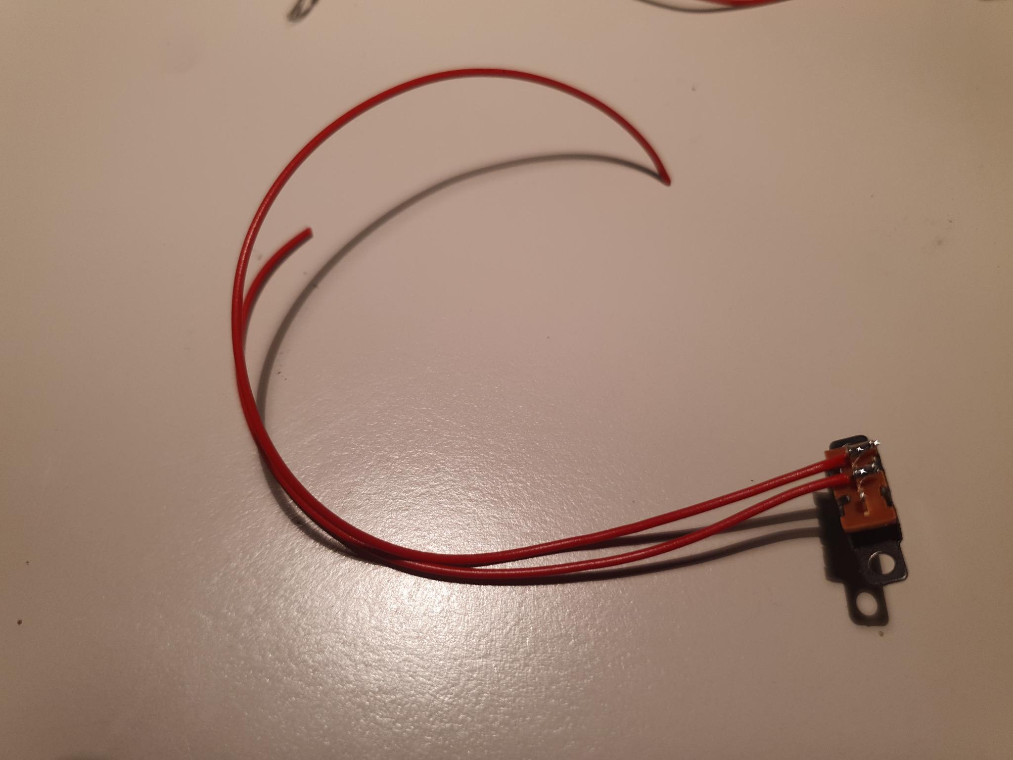
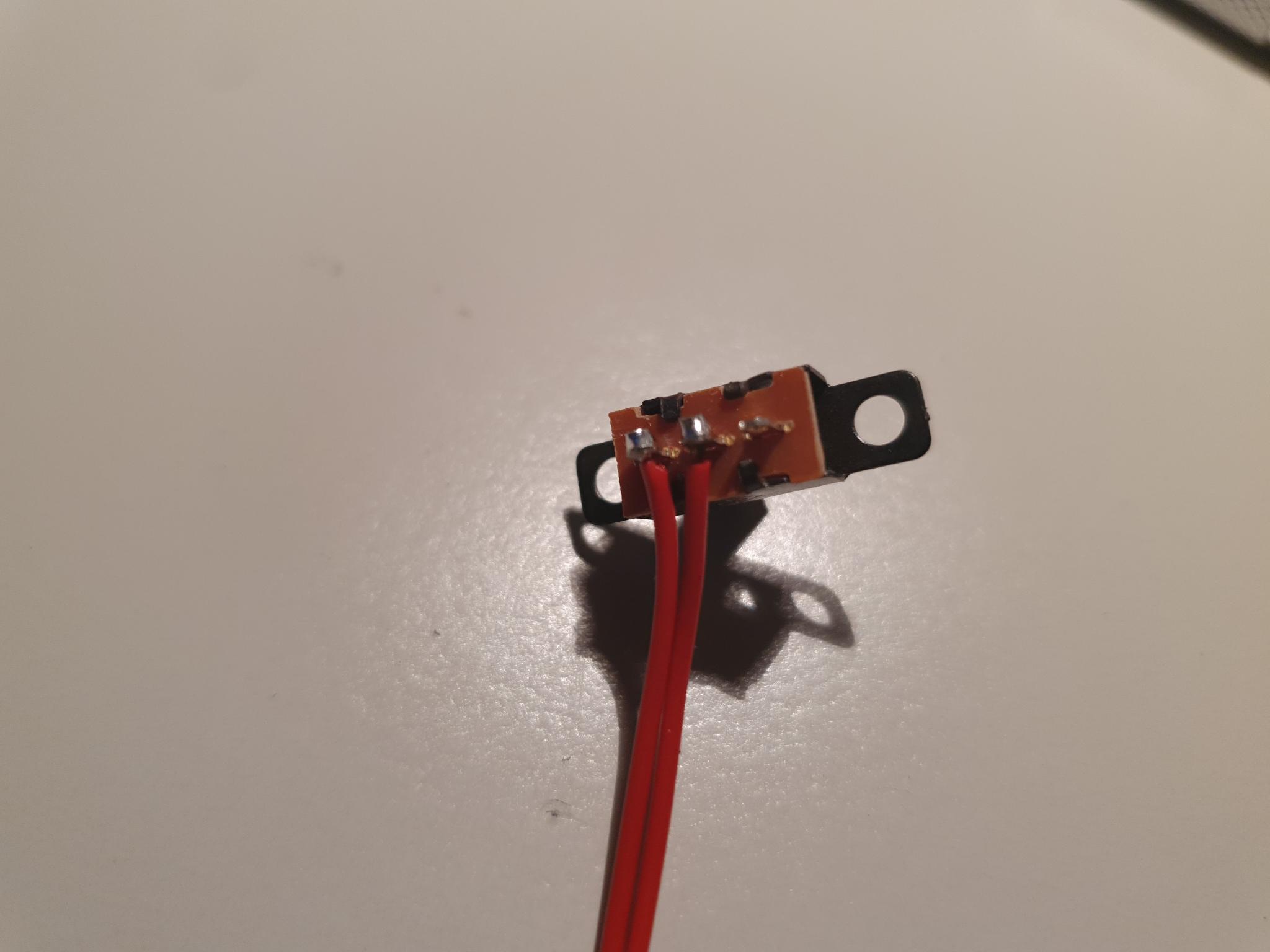
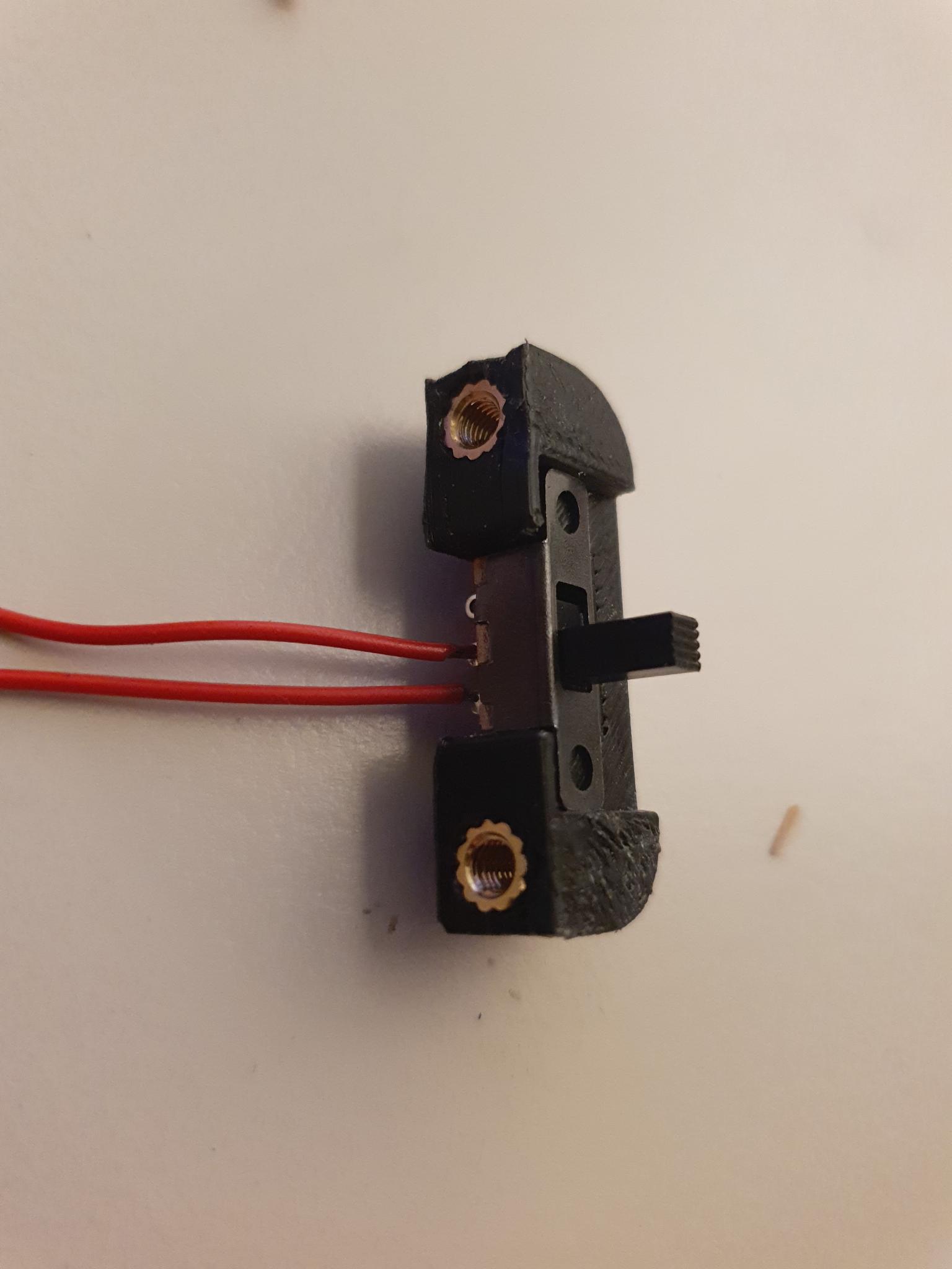
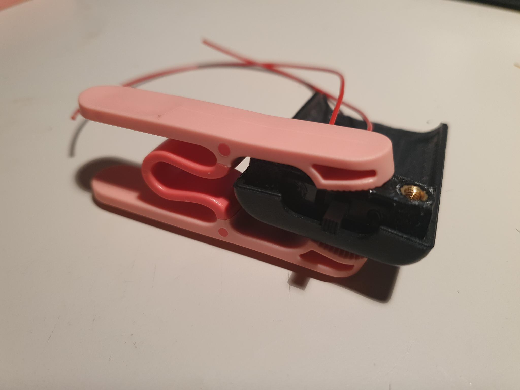
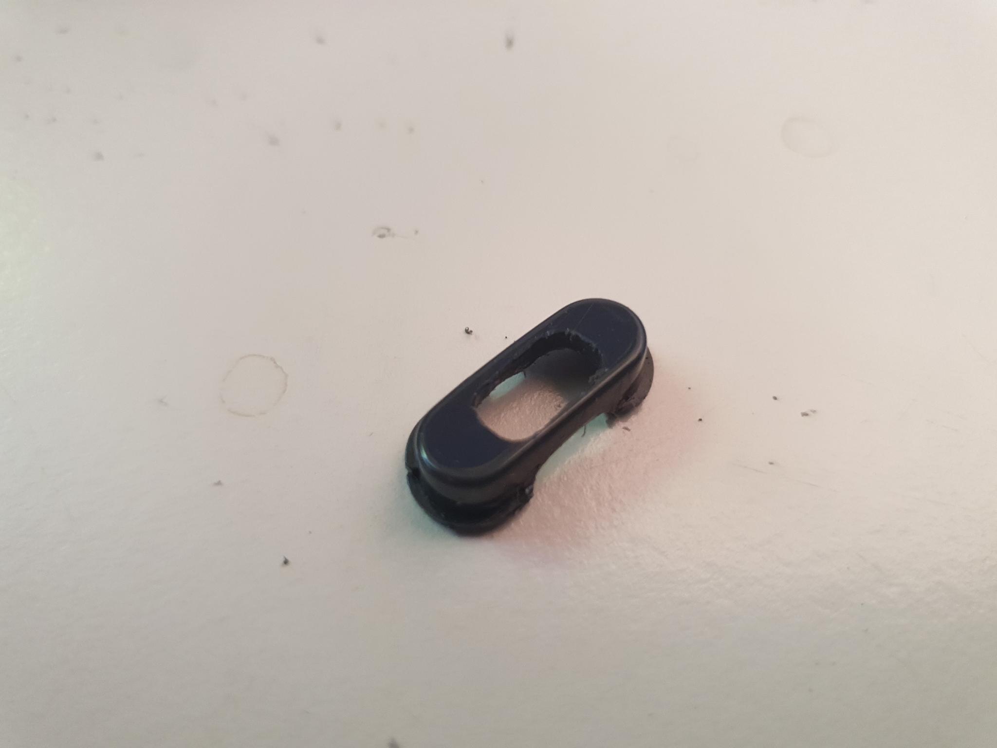
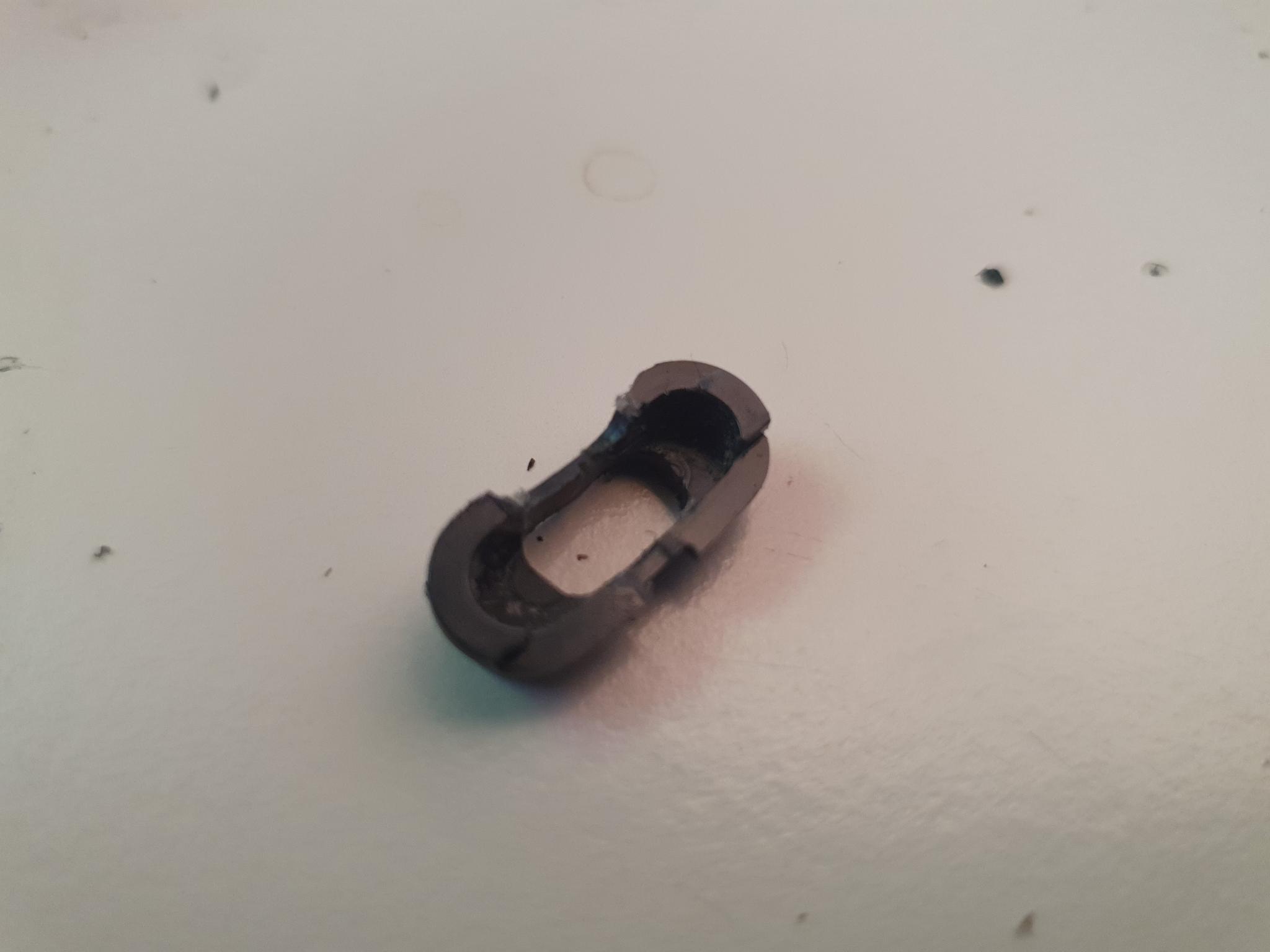
A small sliding switch is prepared.Two wires are soldered in a 90° angle to the switch, a shorter one to the middle, and a longer one to the right side.The soldering contacts can be cut down a bit to not stand out too much.The switch is pressed into the prepared 3D-printed plastic bracket like this.The assembly is placed into the plastic shell like this, it needs to be aligned at the very top.The assembly is glued together using some strong plastic glue or Epoxy. It is important to rough up the surfaces before gluing, to ensure good bonding.A clamp helps with holding while the glue sets.The button saved from before is milled down on its backside, and receives a milled slot into the front for the switch actuator to stick though later.The bottom is cleaned up.
Battery
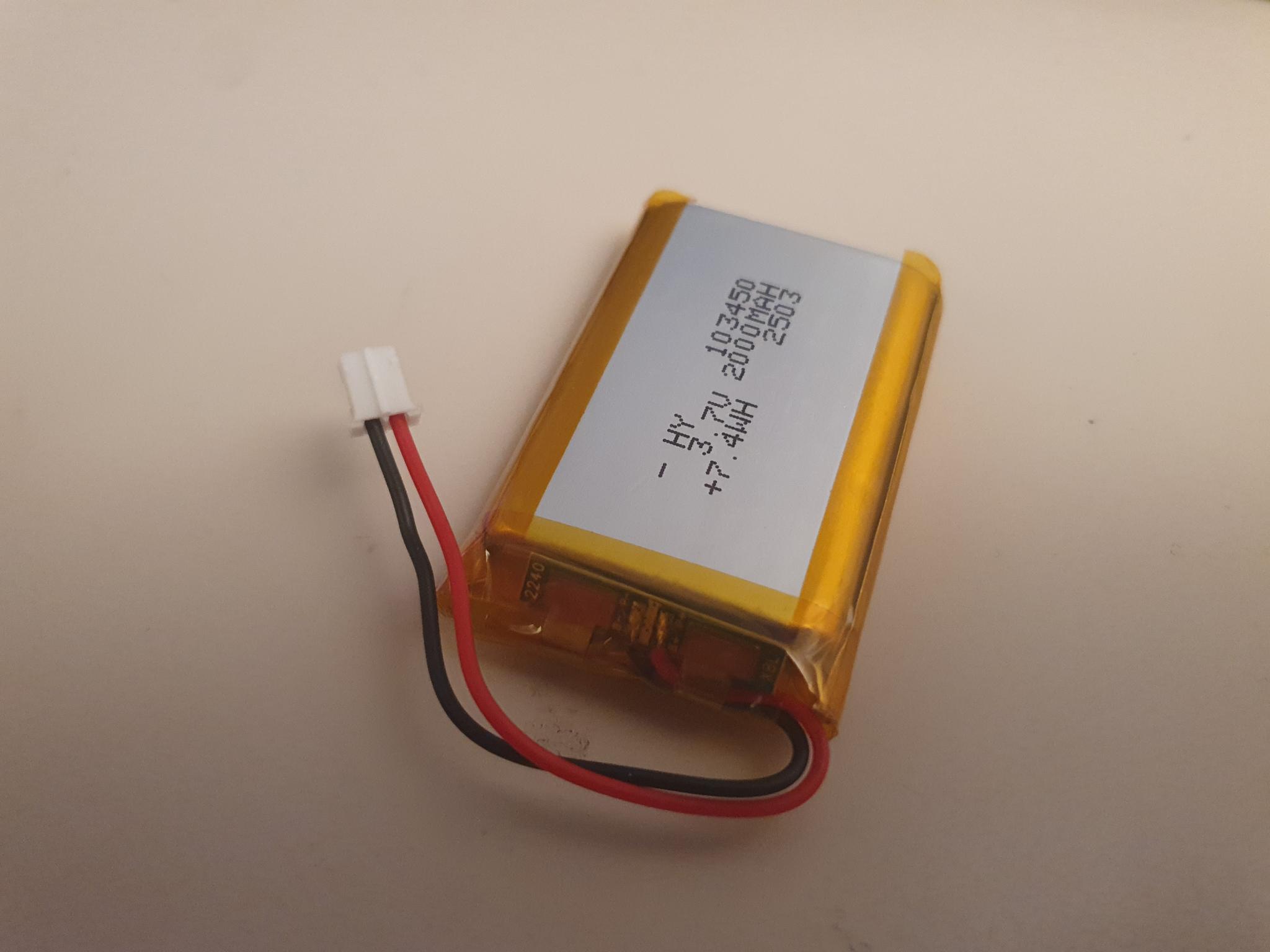
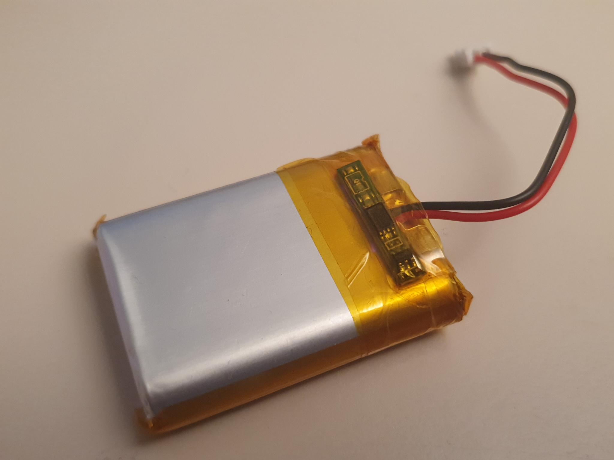
The battery is a very tight fit, and needs some modifications before it can go into the assembly.
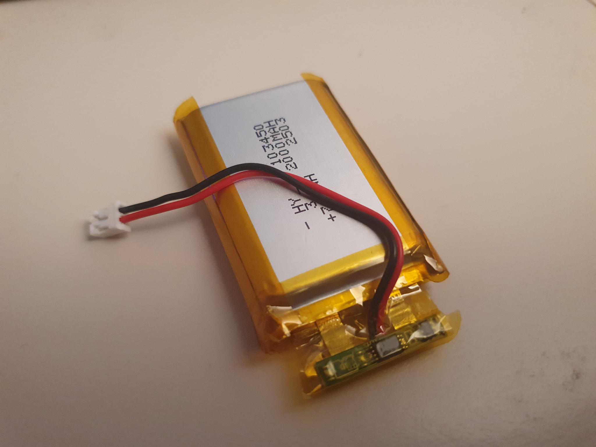
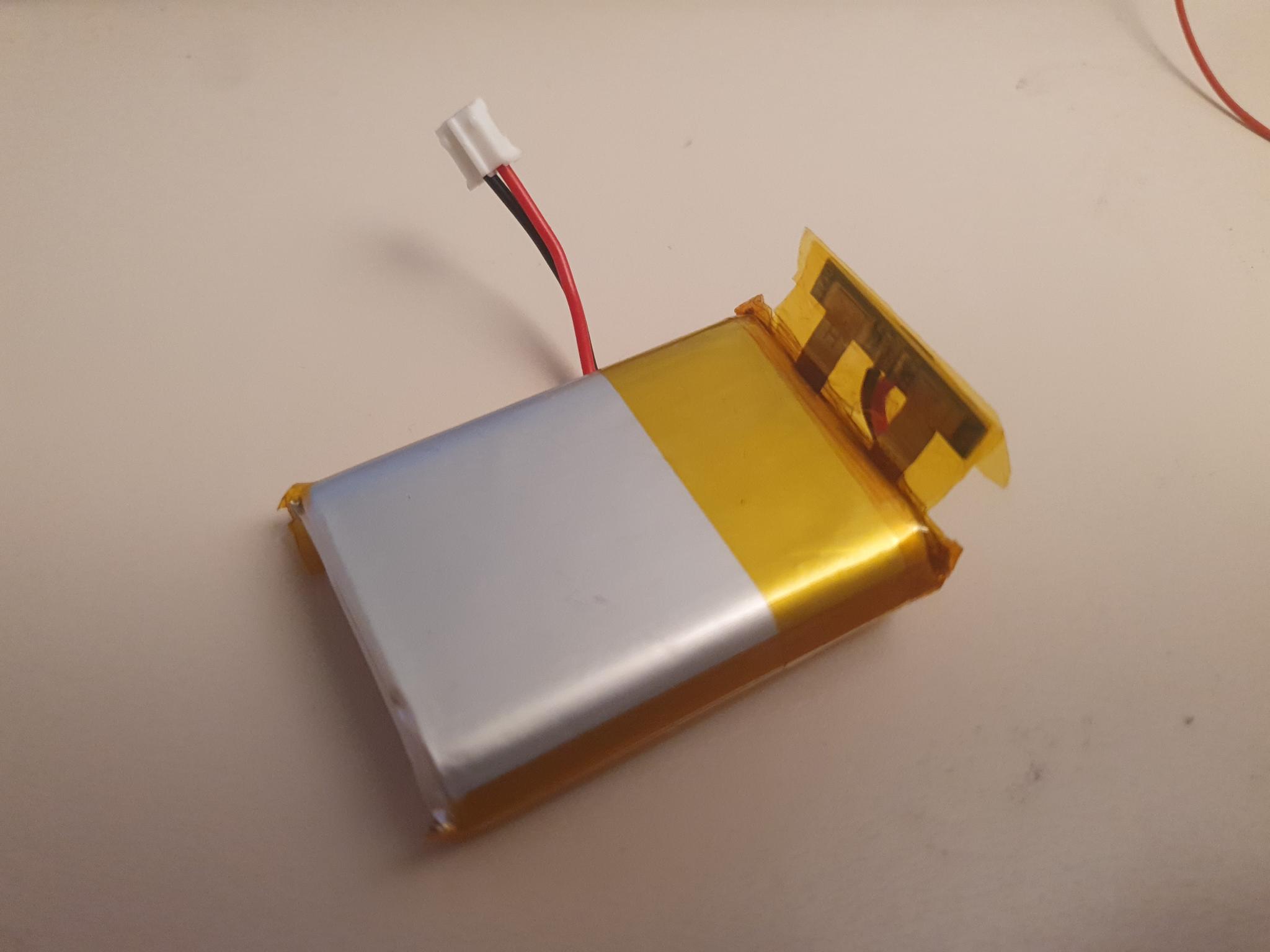
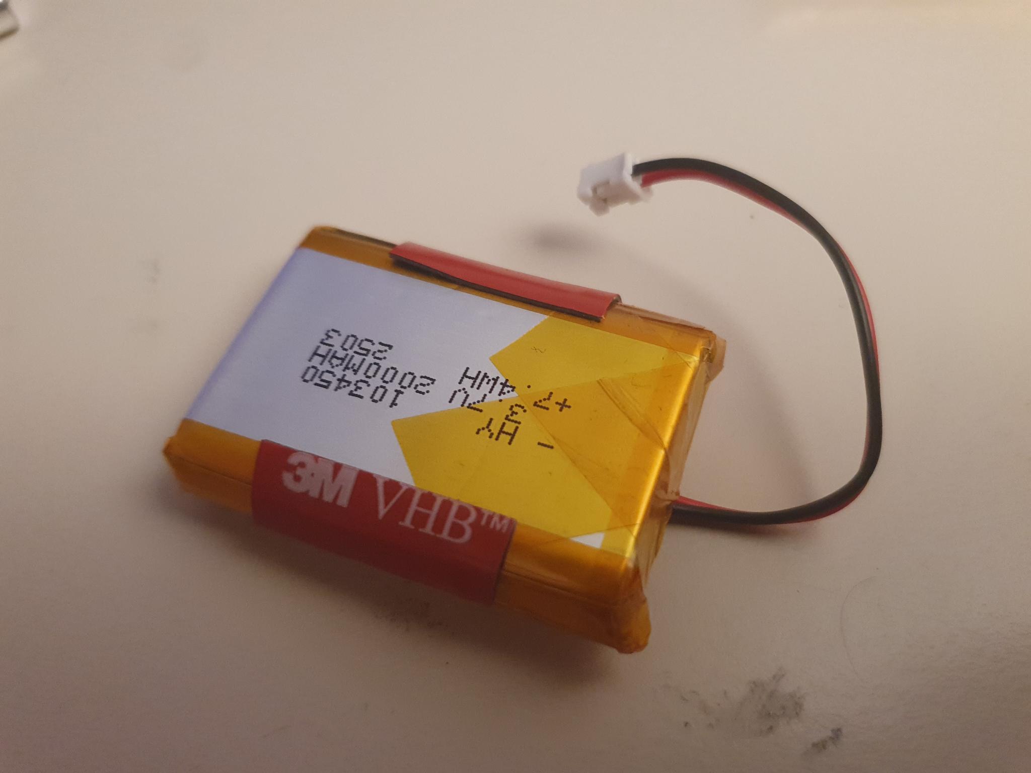
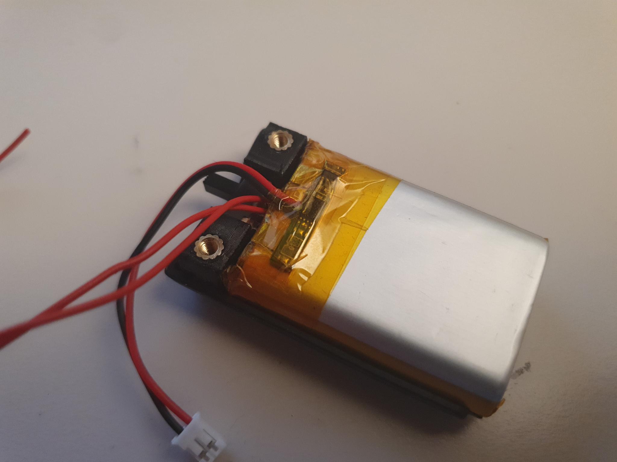
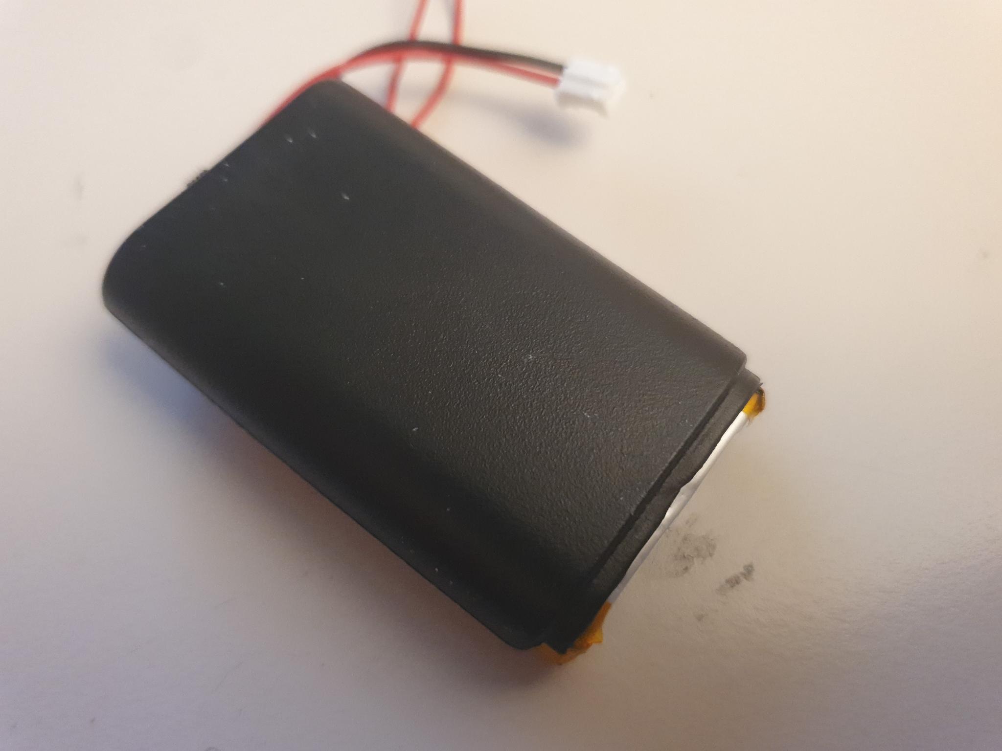
The battery, as it comes from the factory.A careful cut though one side of the protective Kapton tape at the top allows the battery protection circuit PCB to be bent via the battery connection nickel tabs.The protection circuit is folded to the side, and the nickel connection tabs are straightened out using pliers. Make sure to not short them to each other and only work on one at a time.Finally, the protection circuit is folded all the way to to the side of the battery, and everything is insulated and held in place using some more Kapton tape.Next, some VBH double-side adhesive tape is stuck to the lower sides of the battery.These tape strips are then used to stick the battery into the shell assembly.The battery lines up almost perfectly with the bottom edge of the shell. A bit of stick-out is okay, as it will disappear into the controller anyway.
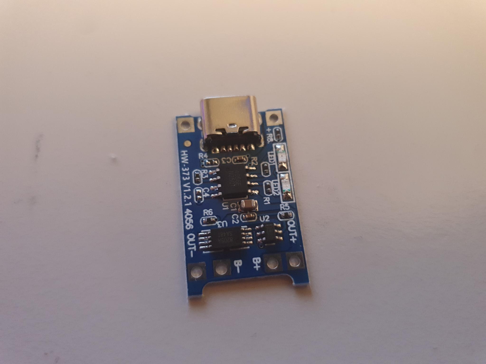
Charging Controller
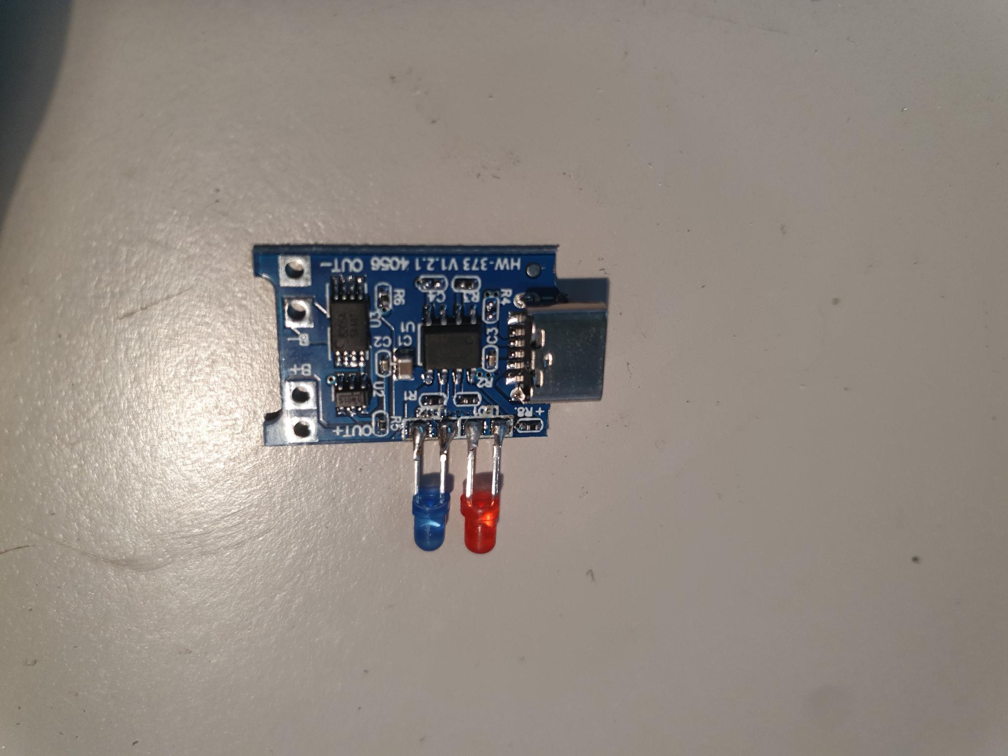
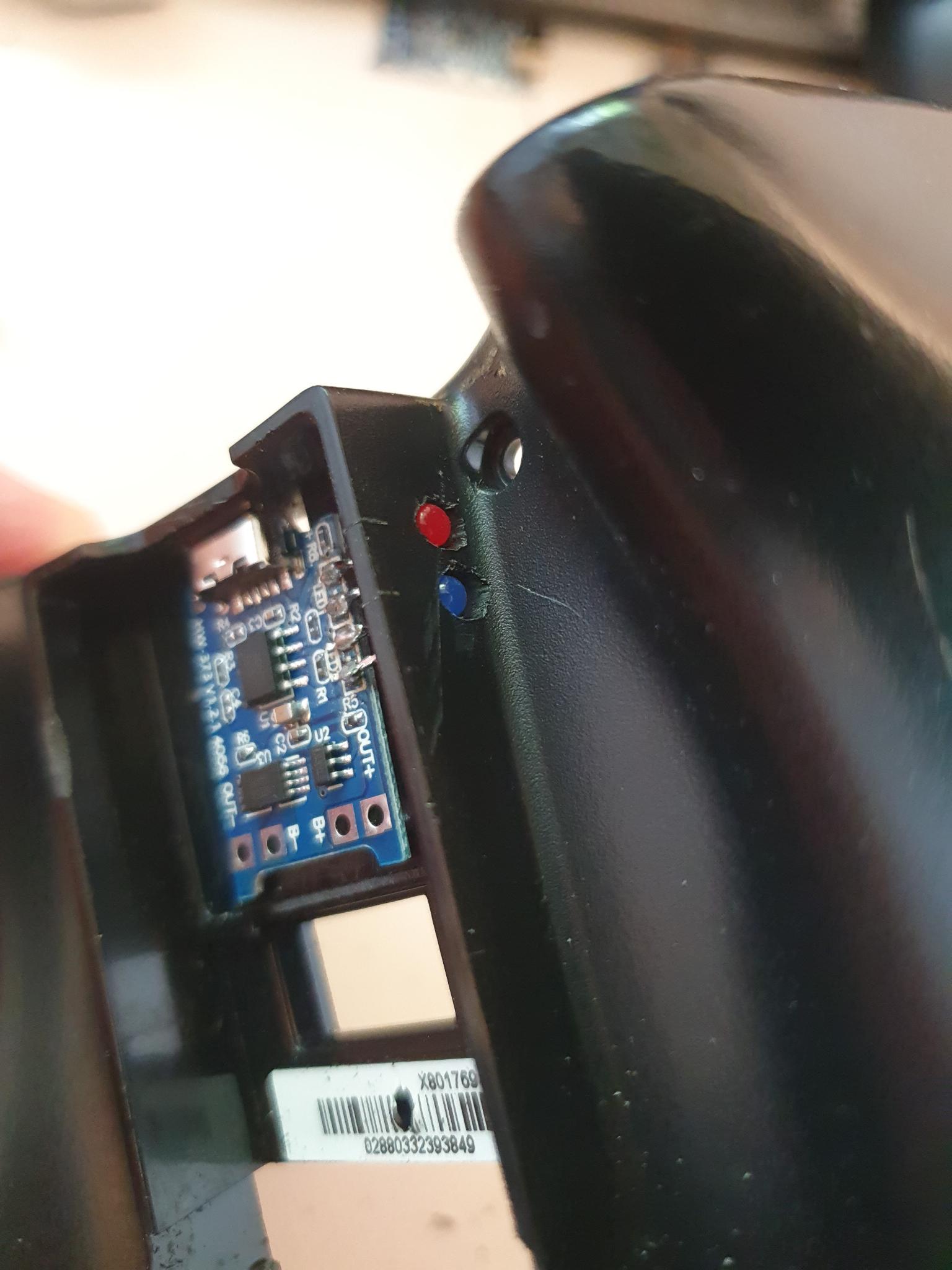
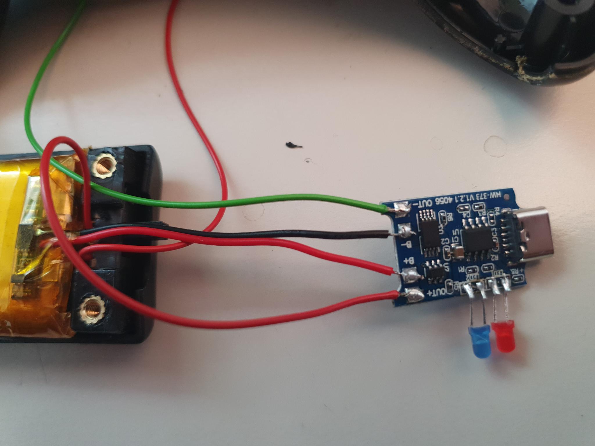
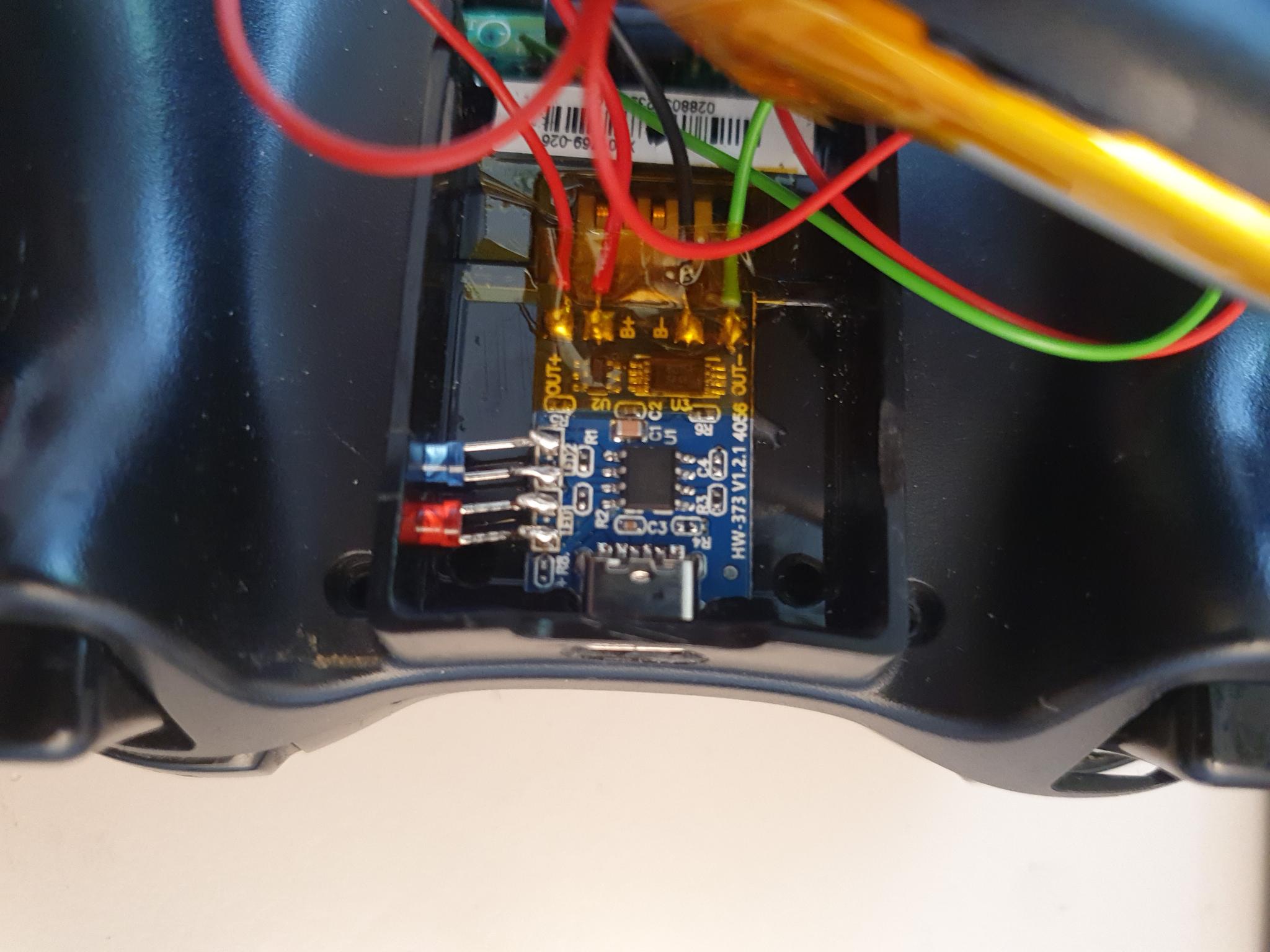
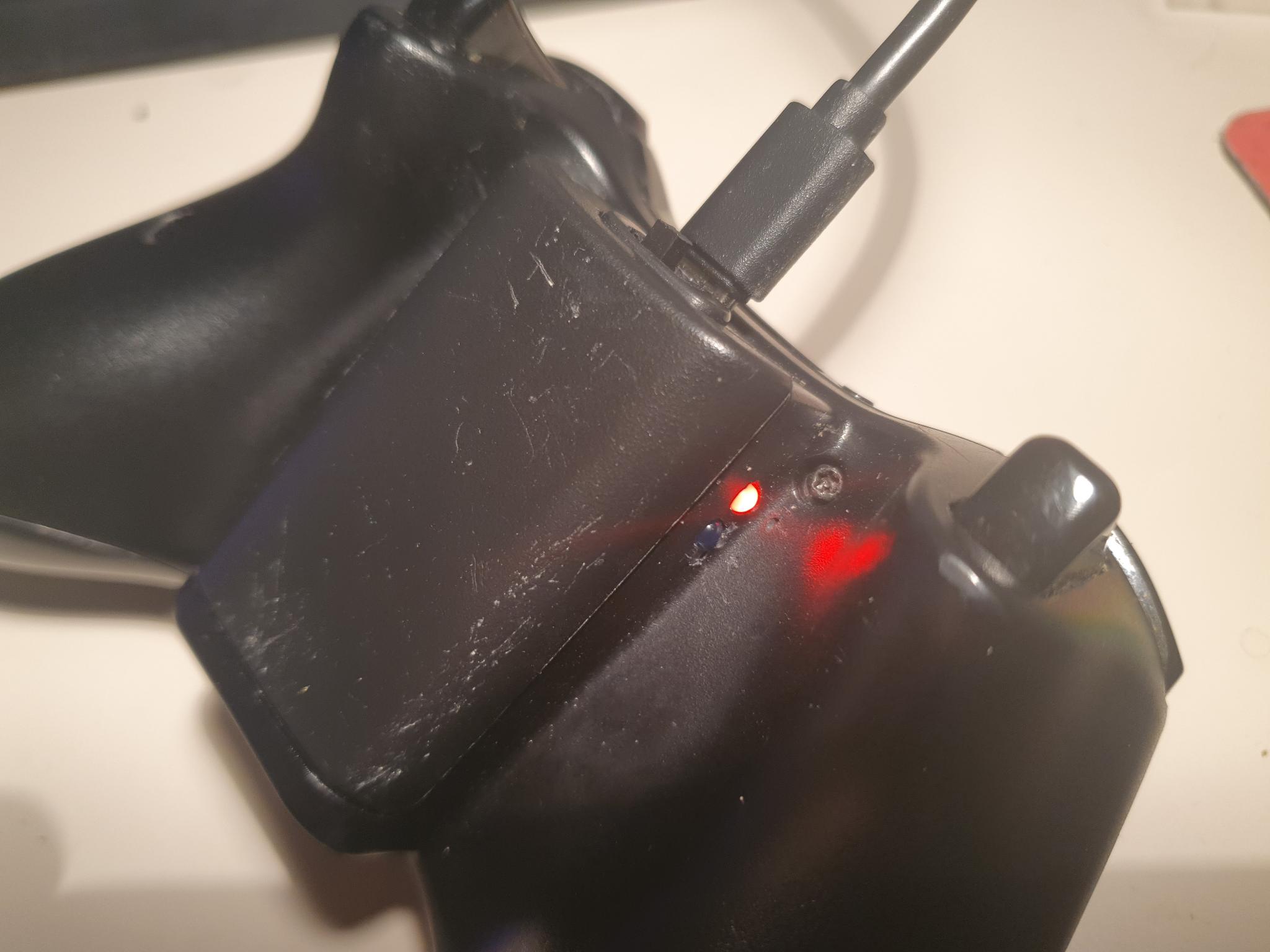
The USB-C charging controller was also modified. I wanted to be able to observe its indicator LEDs from the outside, so I replaces them with wired LEDs.
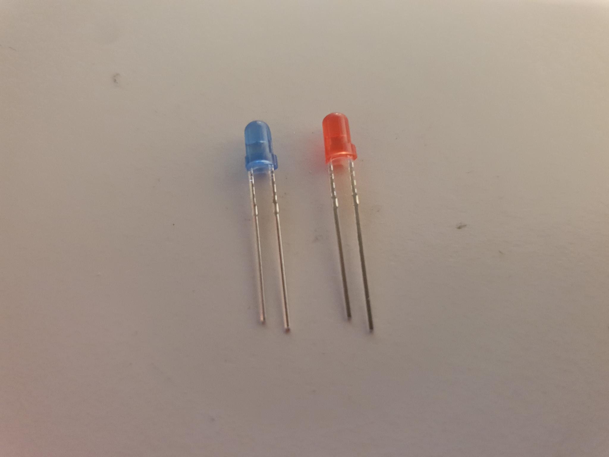
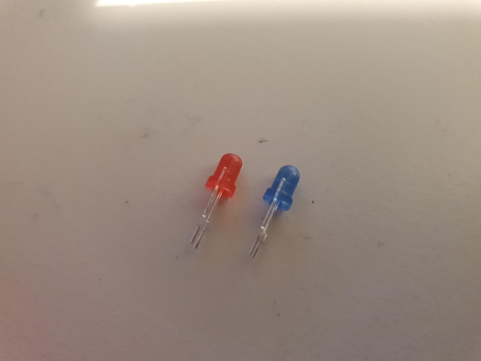
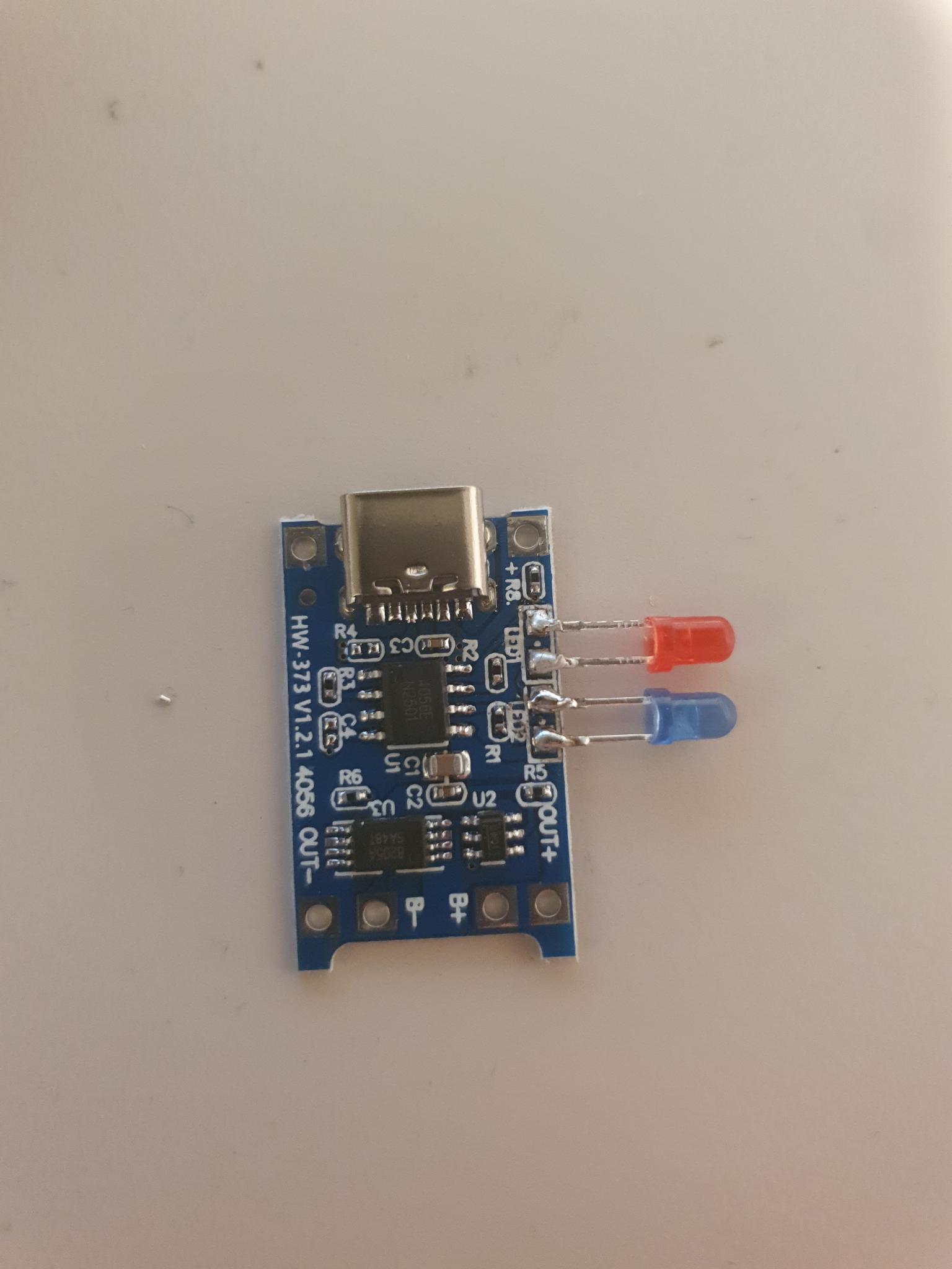
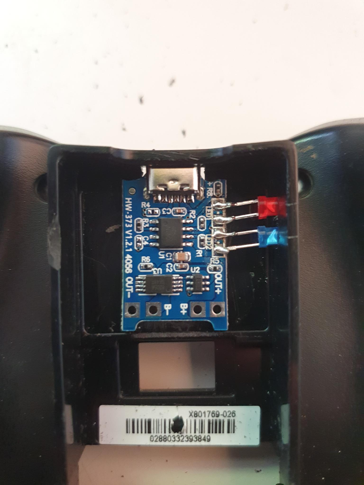
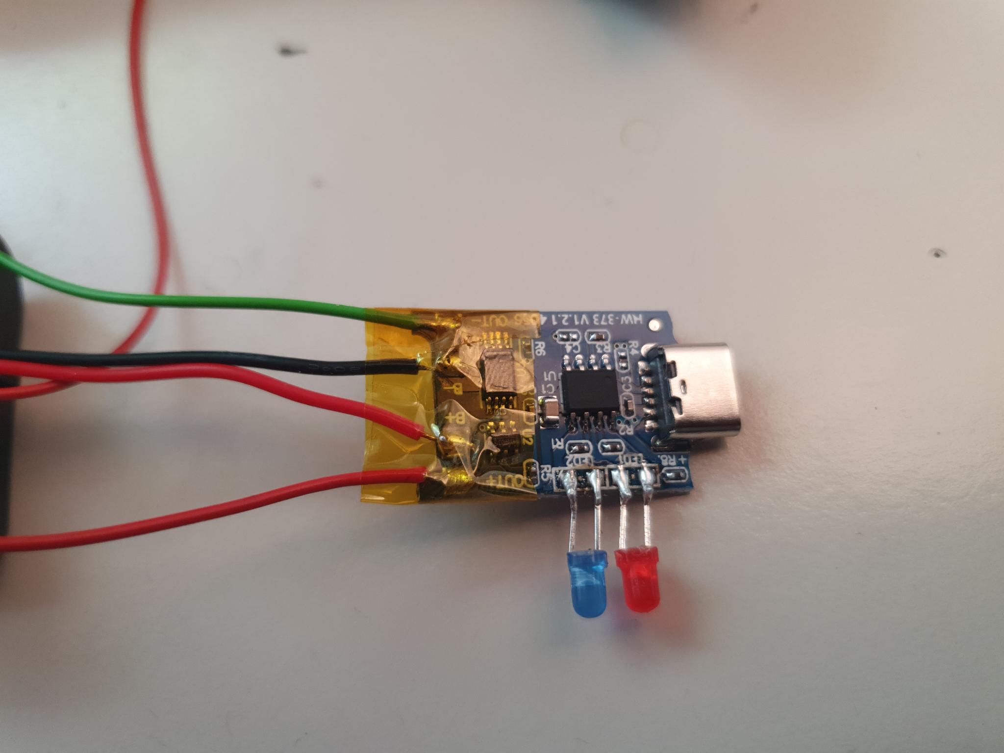
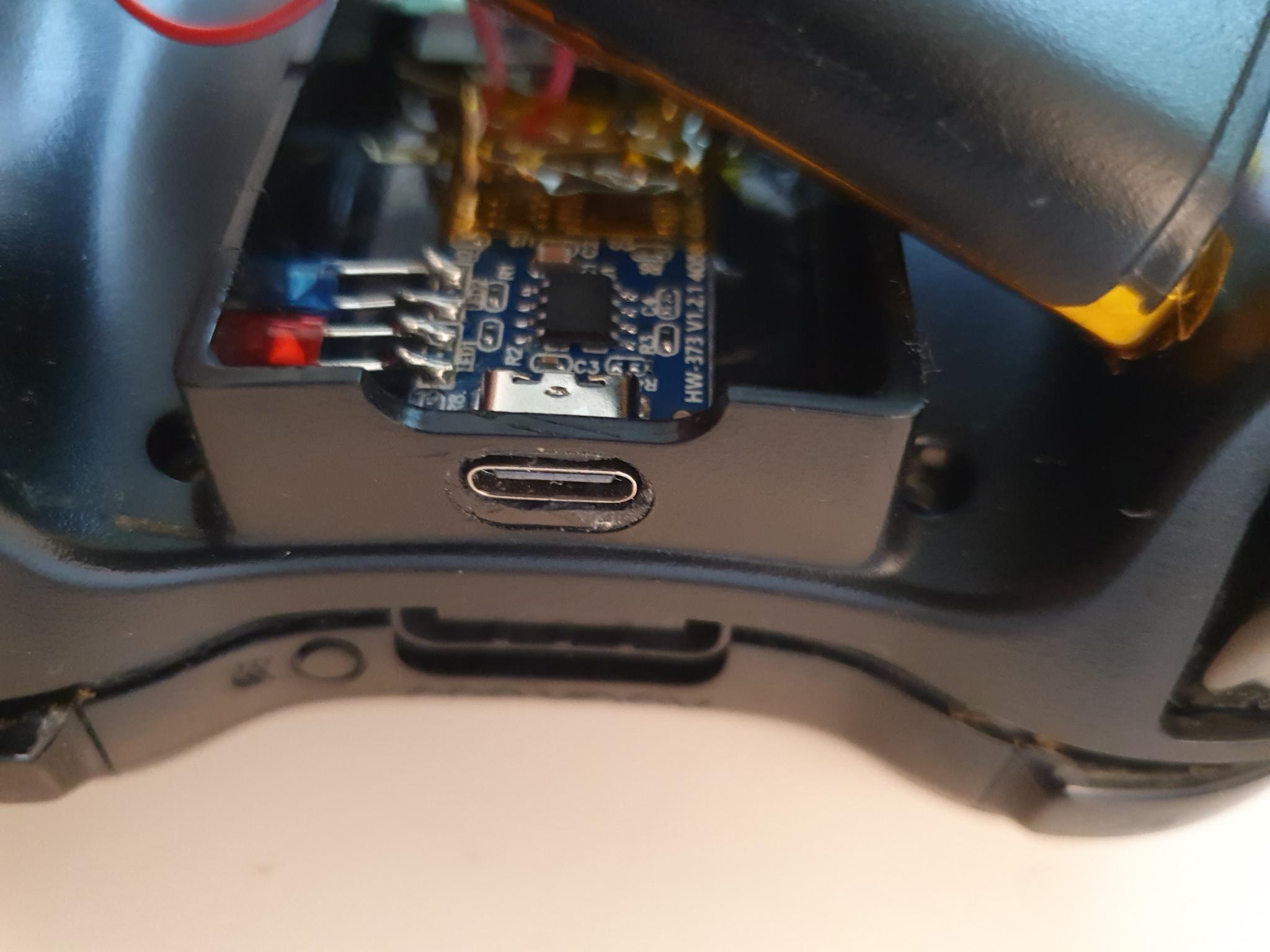
The charging controller, as it comes from the factory.A blue and a red 3mm LED.These need to be cut down such that their legs are around 7mm long.The LEDs are soldered to the charge controller, after the existing SMD LEDs have been removed. Red one has its negative pin on the top, blue one has its negative pin on the bottom. A quick test to see if they light up when USB power is connected is a good idea afterwards.A dremel with a small endmill is used to grind away the two PCB corners next to the USB port.Grinding the PCB smaller allows its port to sit flush with the top side of the controller shell.
Controller Preparation
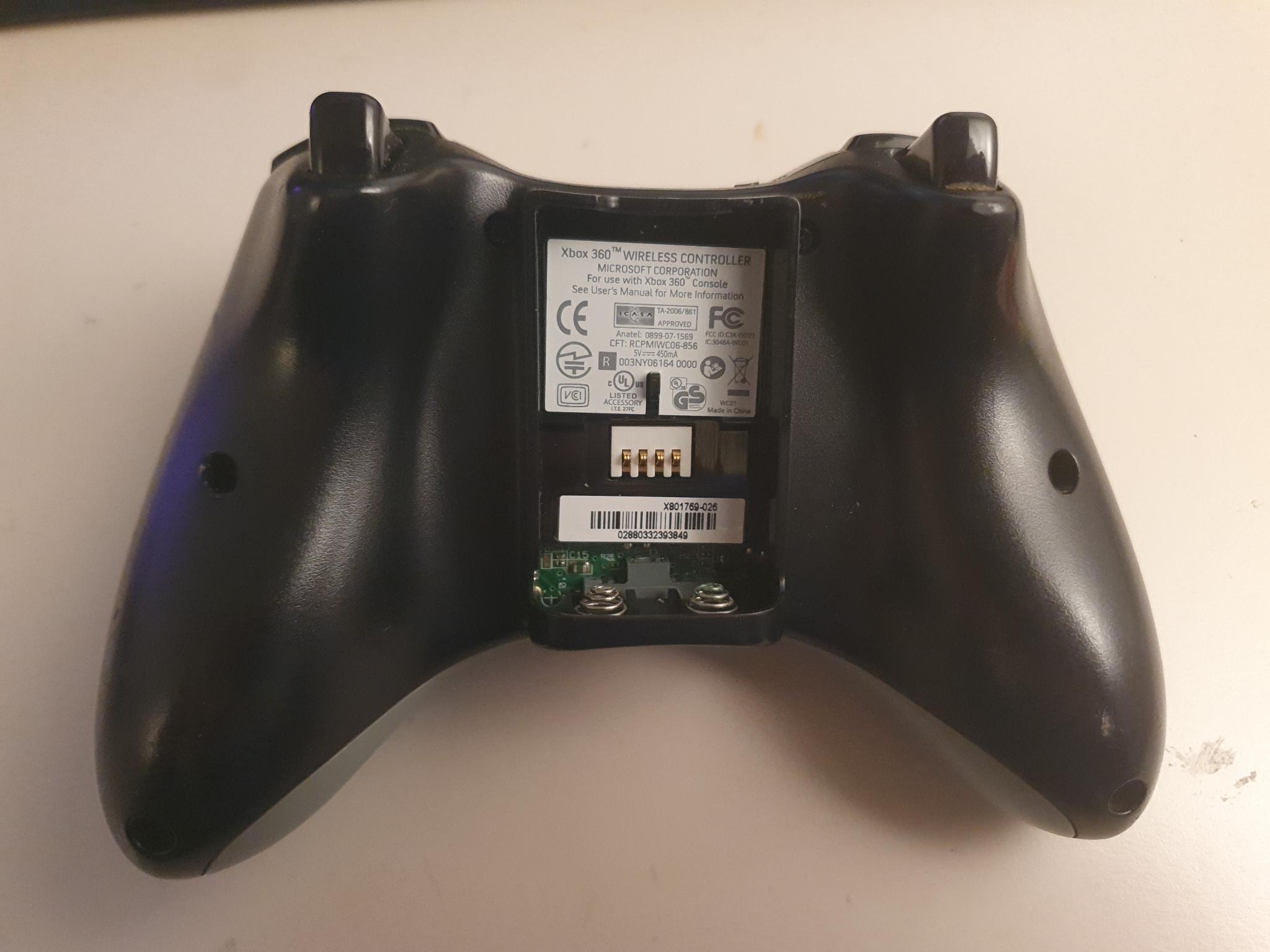
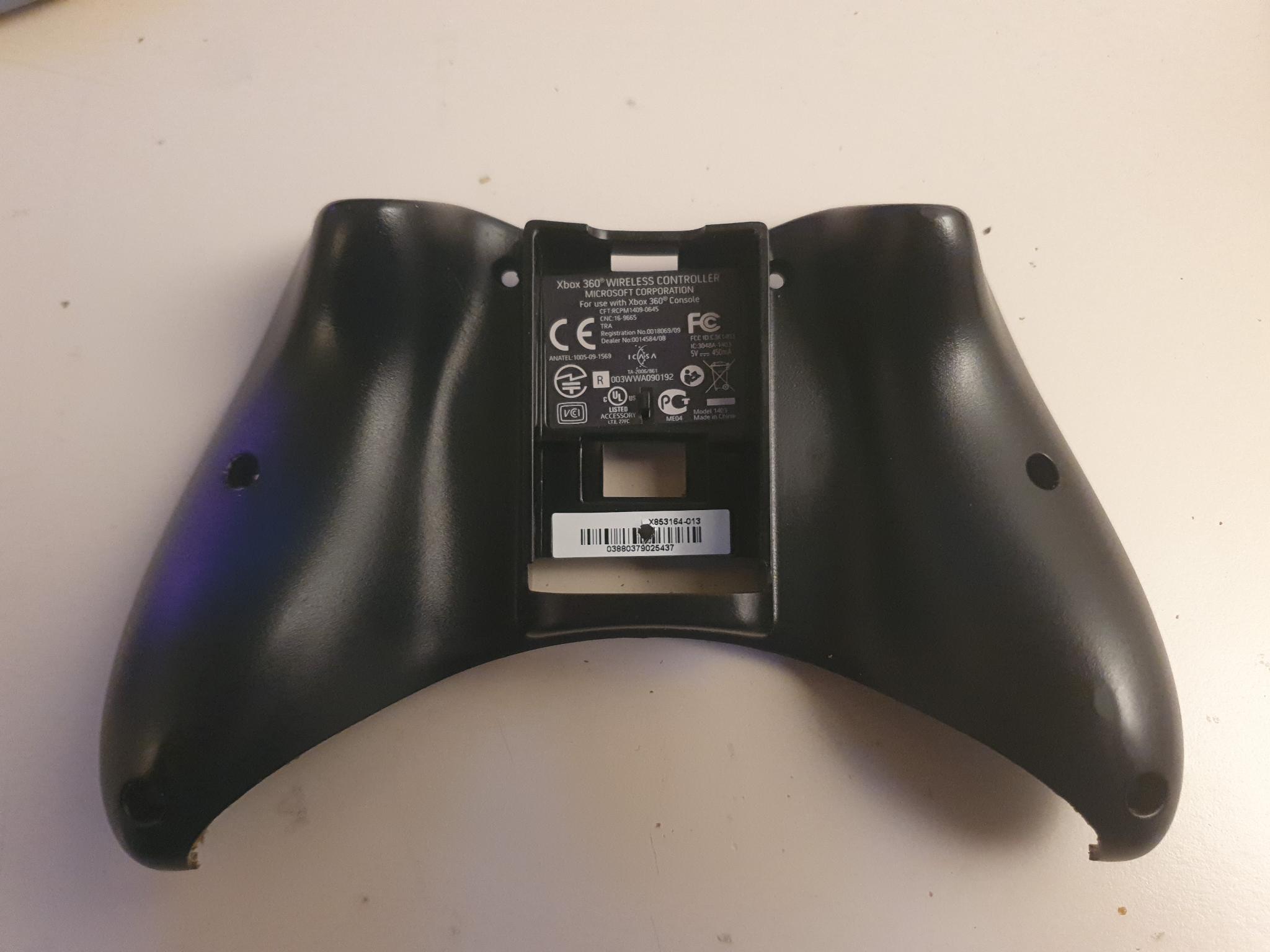
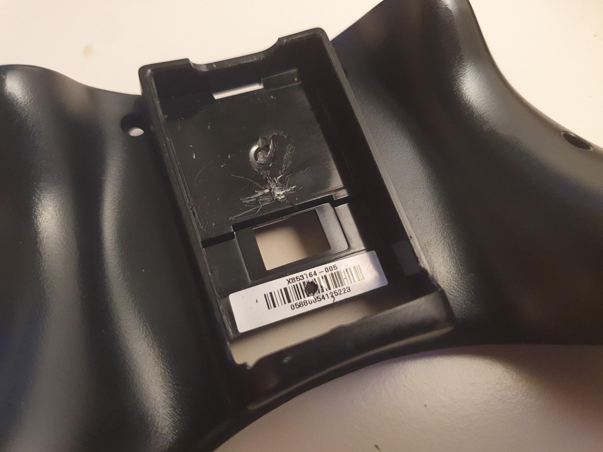
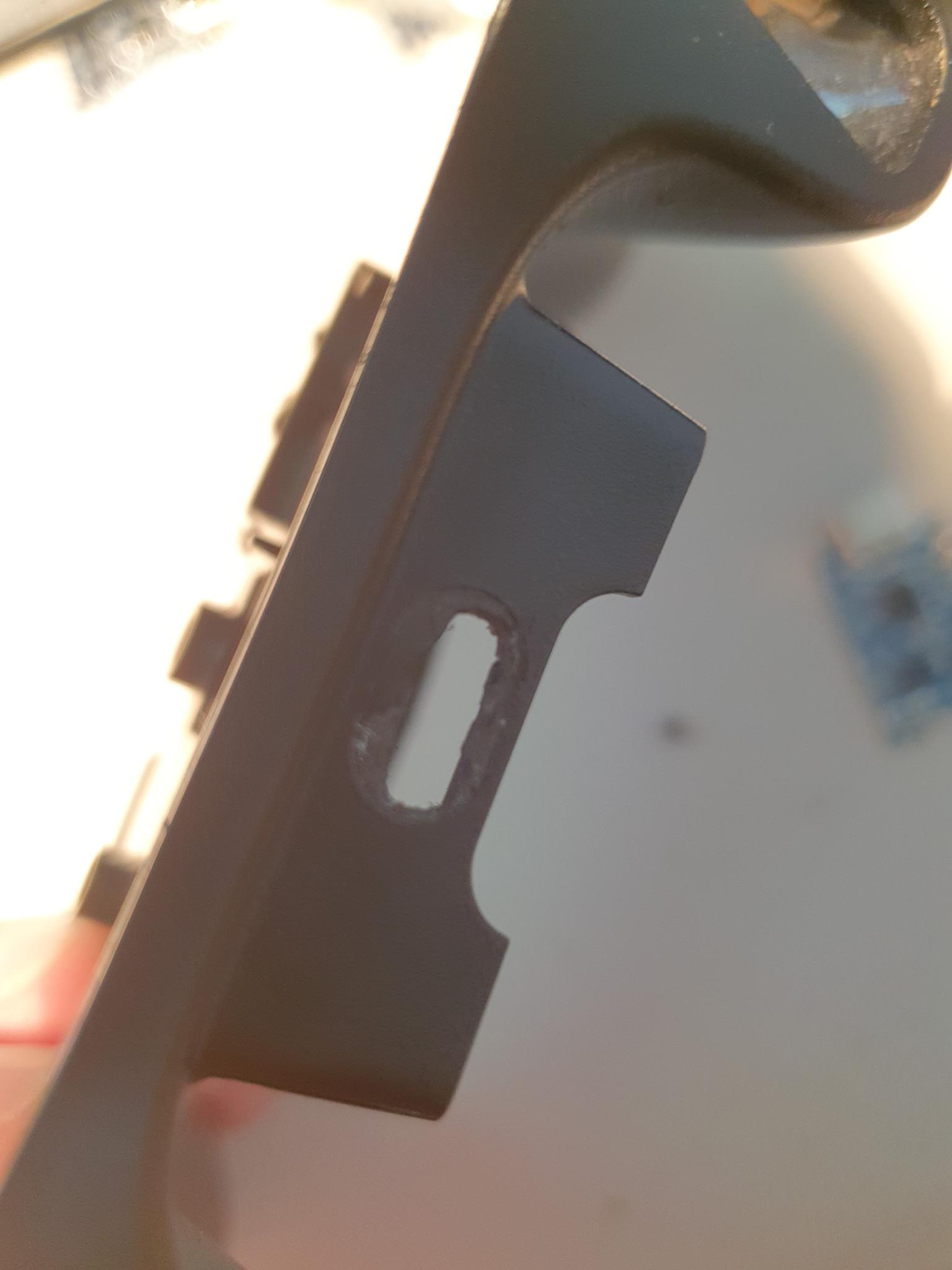
The XBOX 360 controller is disassembled and slightly modified.
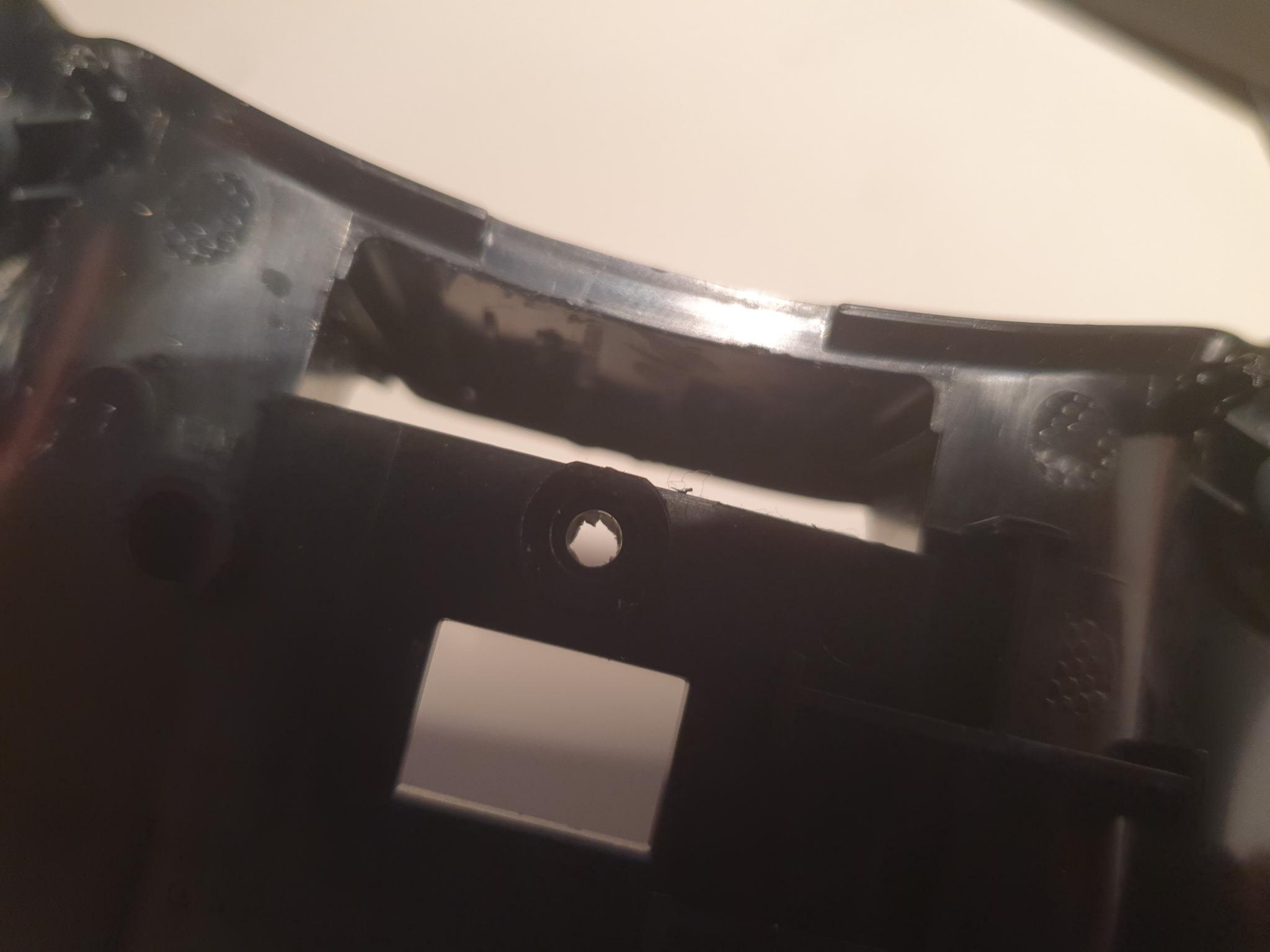
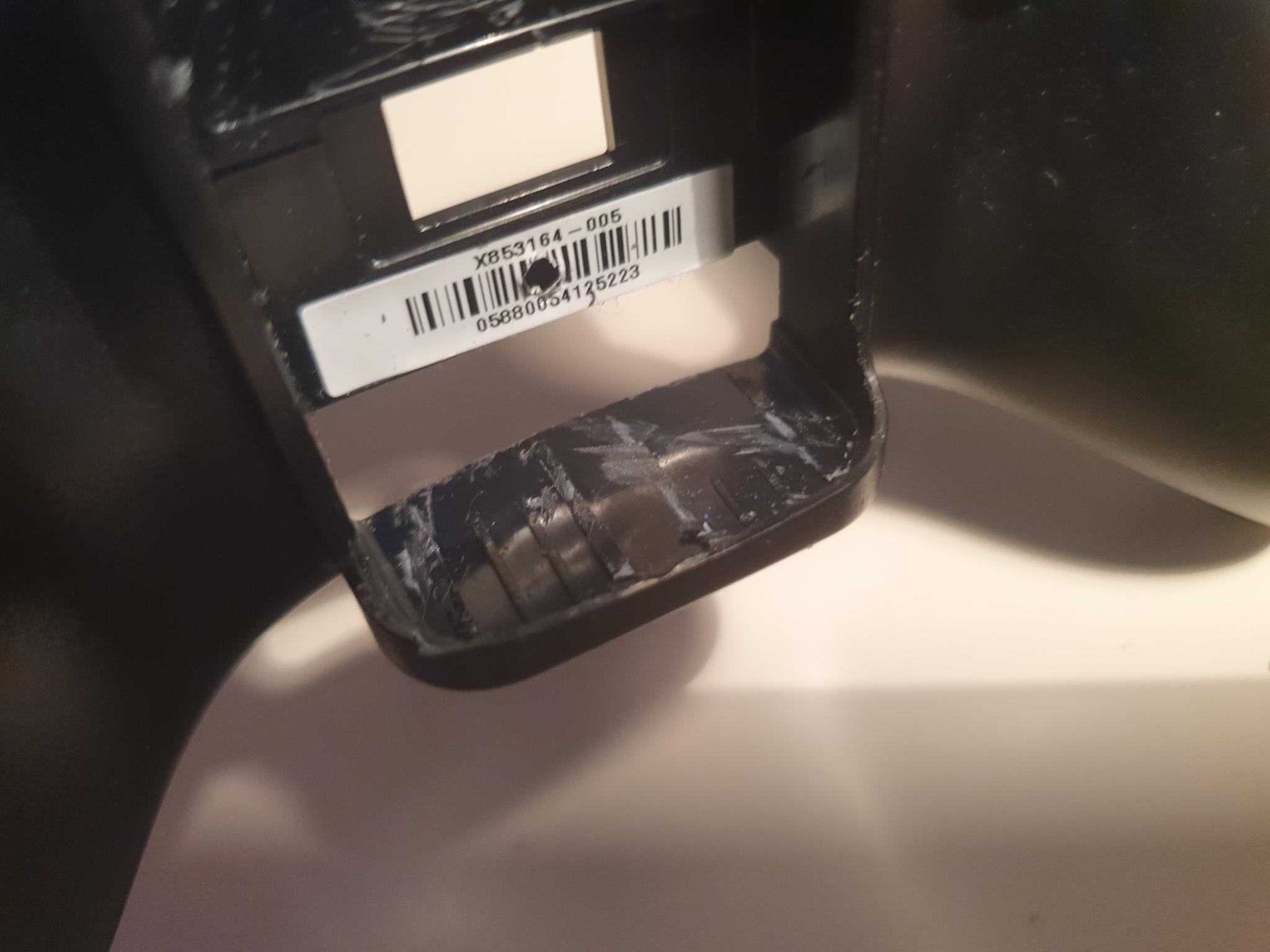
First, seven screws are removed. One hides behind the barcode sticker.Carefully remove the backplate of the controller, without letting the front assembly fall into its many pieces.The backplate is now removed.The little center tab / nose in the middle of the battery compartment needs to be cut and ground away.These small ribs at the bottom of the battery compartment also need to be cut and dremeled away to make room for the battery.It does not need to be perfectly smooth.The 3D-printed part from before (before inserting the heatset inserts) is used as a drill pattern for a 3mm drill. Two holes are drilled though.These two holes will be used to hold the battery pack from the inside.The dremel is used to mill a slot into the place where the holographic sticker used to sit.This slot will be used to fit the USB-C socket.In addition, two holes are drilled from the inside out to accept the two LEDs of the charge controller.
Soldering and Assembly
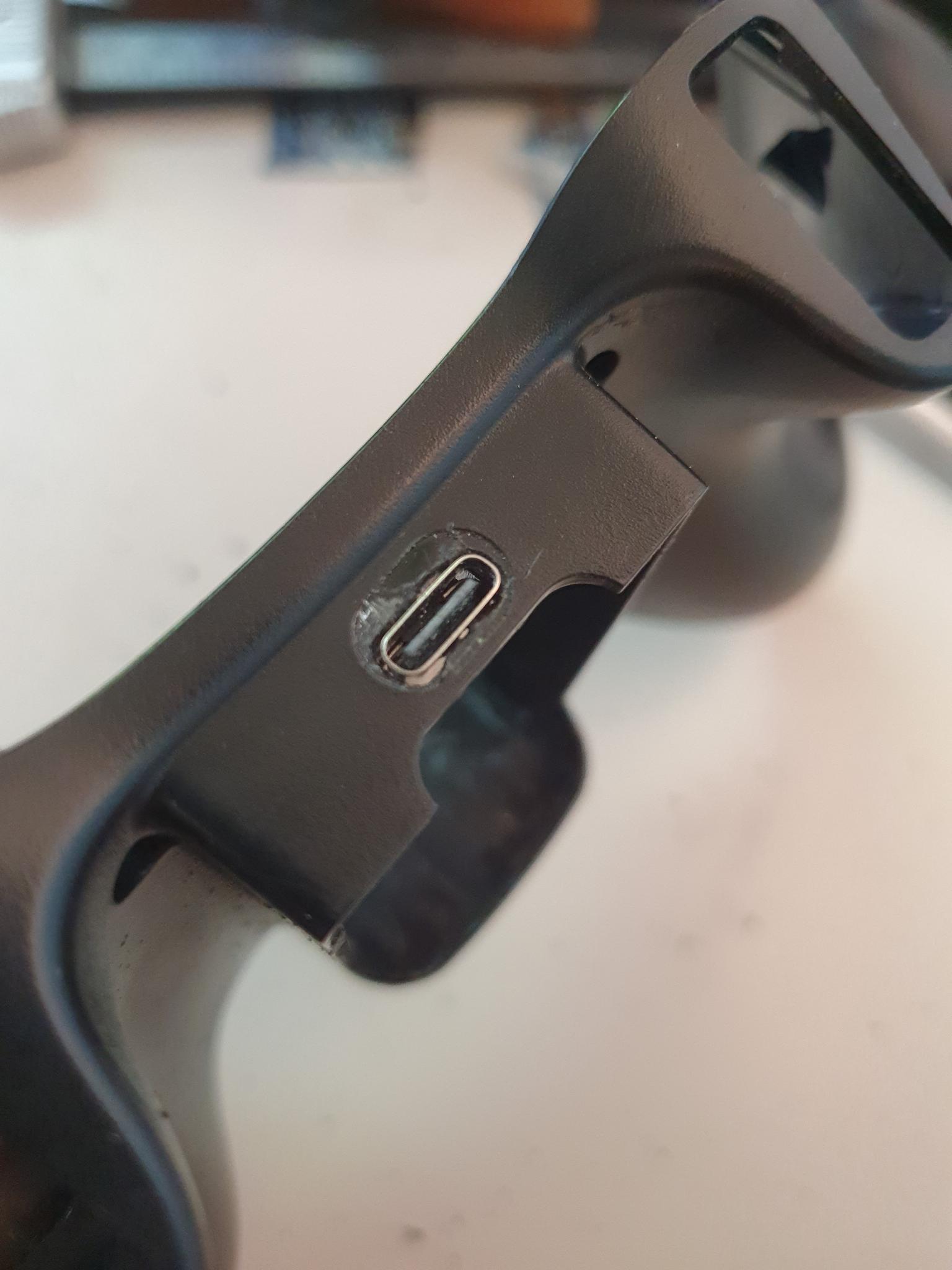
Finally, all the parts are put together.
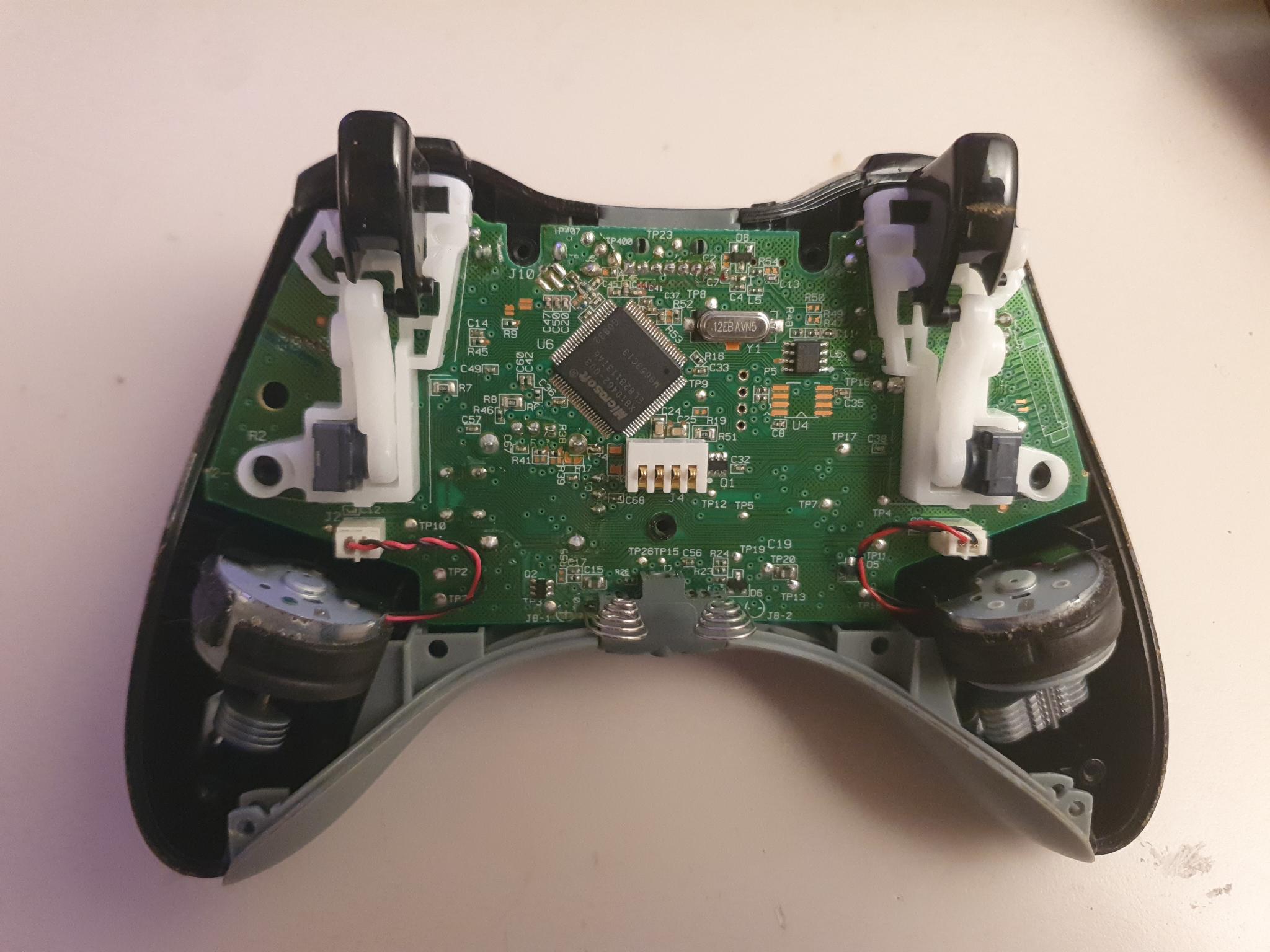
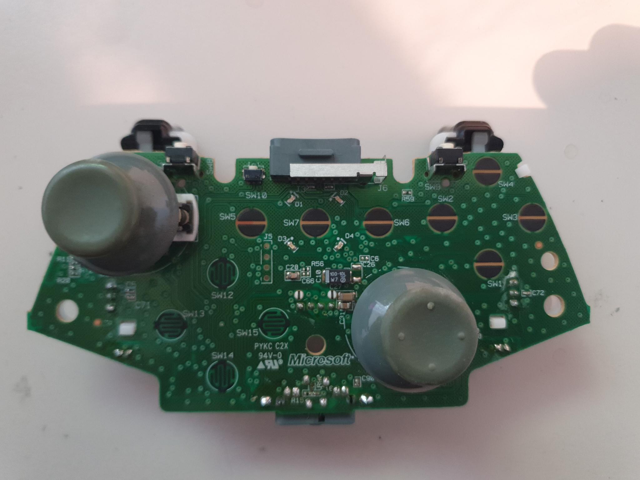
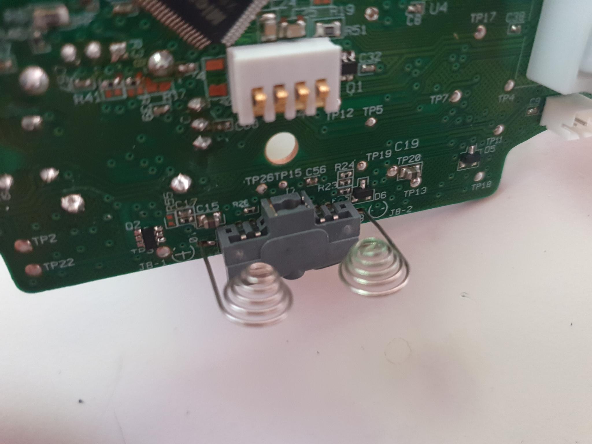
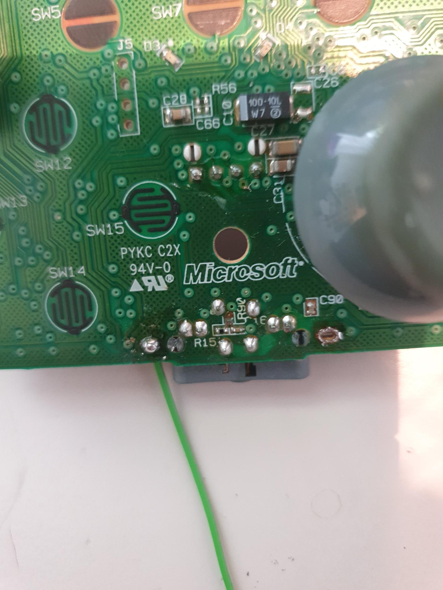
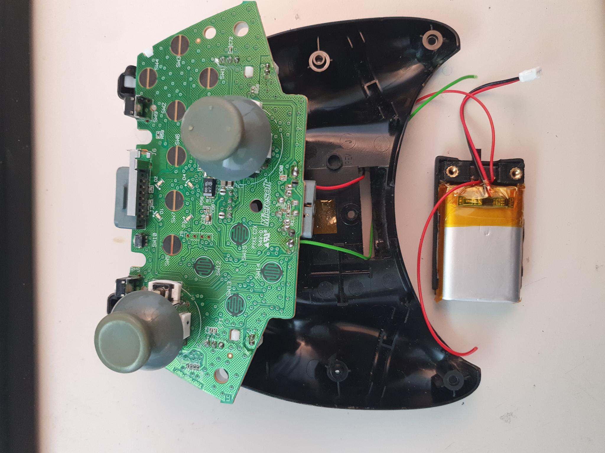
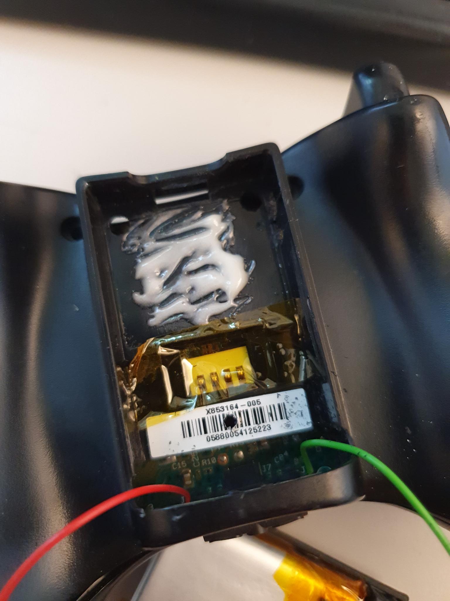
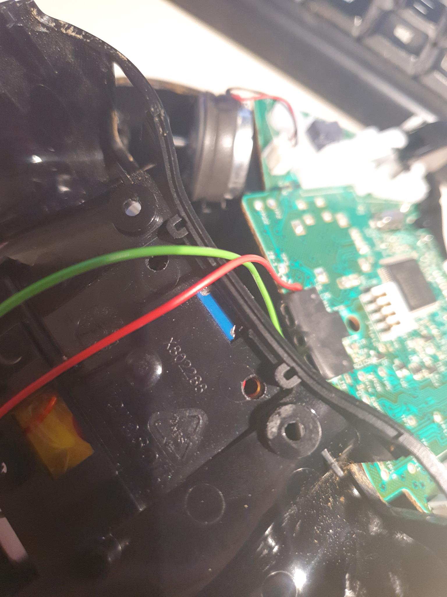
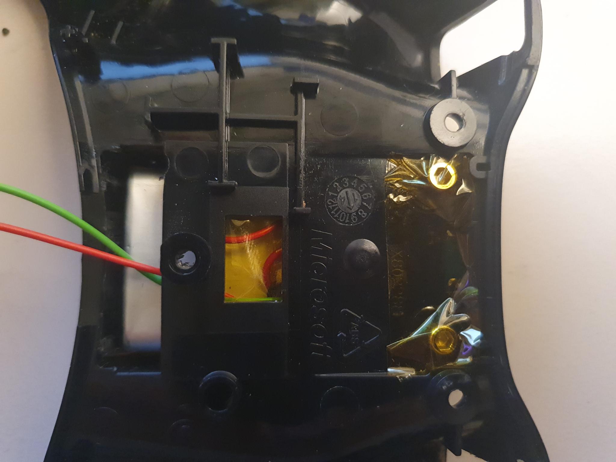
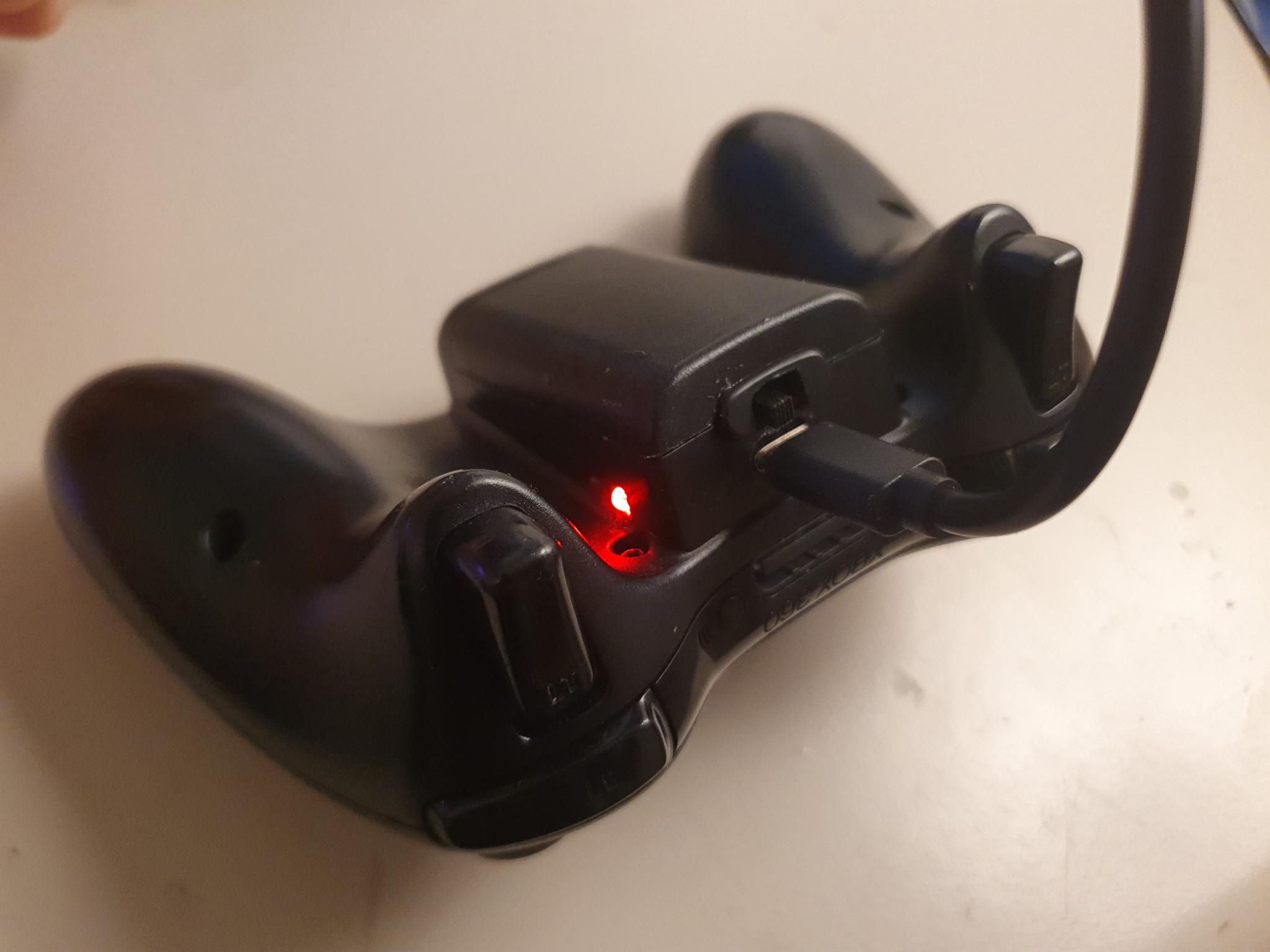
But first, the controller mainboard needs to be modified a bit.These two battery spring contacts are desoldered and removed.Instead, wires are fed though the contact holes and soldered on the front.The negative green wire is threaded through the big bottom hole of the controller plastic backplate. The longer red positive cable coming from the power switch is threaded though the same hole from the other side and soldered to the positive terminal on the controller mainboard.Next, the battery charger is soldered to the battery, and the shorter positive cable from the switch is soldered to the positive out pin of the charger. The negative cable coming from the controller is soldered to the negative out pin of the charger.The solder contacts of the charger are wrapped with Kapton tape for protection.The internal spring contacts of the controller are protected with some Kapton tape, and glue is applied to the upper part of the battery compartment.The charging module is glued into the controller backplate such that the USB-C socket and the LEDs slide into the provisioned holes.The USB-C socket should sit flush with the top side of the controller backplate.The button with the slot is fitted around the sliding switch actuator.The drilled holes line up with the heatset inserts. Two 10mm M3 hex bolts are used to screw the battery back together with the controller backplate. They must not be over-tightened or else they might rip the 3D-printed part out of the battery pack shell.The bold heads are covered with Kapton tape for insulation.The controller is reassembled. Free movement of the power switch is checked.The red LED lights up during charging, the blue one once it is full.The controller can also be used while it is charging.