
Of course, there is always a Need for Speed in racing simulations. But sometimes, there is also the Need for Smooth Drifting Around Tight Corners. And pressing a button on my steering wheel controller just doesn’t cut it in terms of control and realism.
So, I set out to acquire a handbrake controller, but quickly decided to build my own after seeing the retail prices often above 80€. Surely I could build something equivalent similar out of parts lying around?
Inspiration
Originally, I wanted to build a system similar to a classic handbrake in a commercial car:

Image source: Wikimedia commons.
But this quickly proved to be a challenging build, because I wanted to clamp the thing to my table. So instead I opted to a vertical design, which is often found in racing / drift cars hydraulic systems:

Image source: ASD Motorsports.
The mechanical build
After an inventory check of what parts I had lying around, I drew a quick and dirty CAD model:
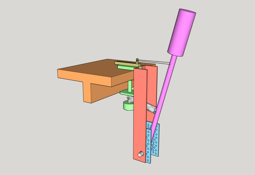
I used a spare Actobotics rail (blue) from a previous project to mount a bearing for the lever (violet). The rail is then screwed to two L-shaped pieces of aluminum (red), which in turn are screwed to a desk clamp (green). The lever then actuates a linear potentiometer (yellow), which is mounted on top of the clamp. A spring (silver) provides the “mechanical feedback” to the user and also limits the amount of travel so the potentiometer does not break.
All in all, the build went about 95% to plan. Some small adjustments had to be made, but in the end it worked out fine.
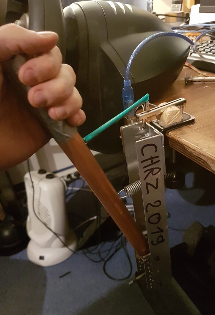
Open position 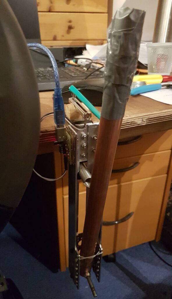
Closed position
The Electronics
So, the next problem was somehow getting the movement data into the computer. For this, I designed and built a small PCB which presents the potentiometer data via USB to the computer. The circuit is fairly simple, all the logic is handled by an ATtiny85 microcontroller.
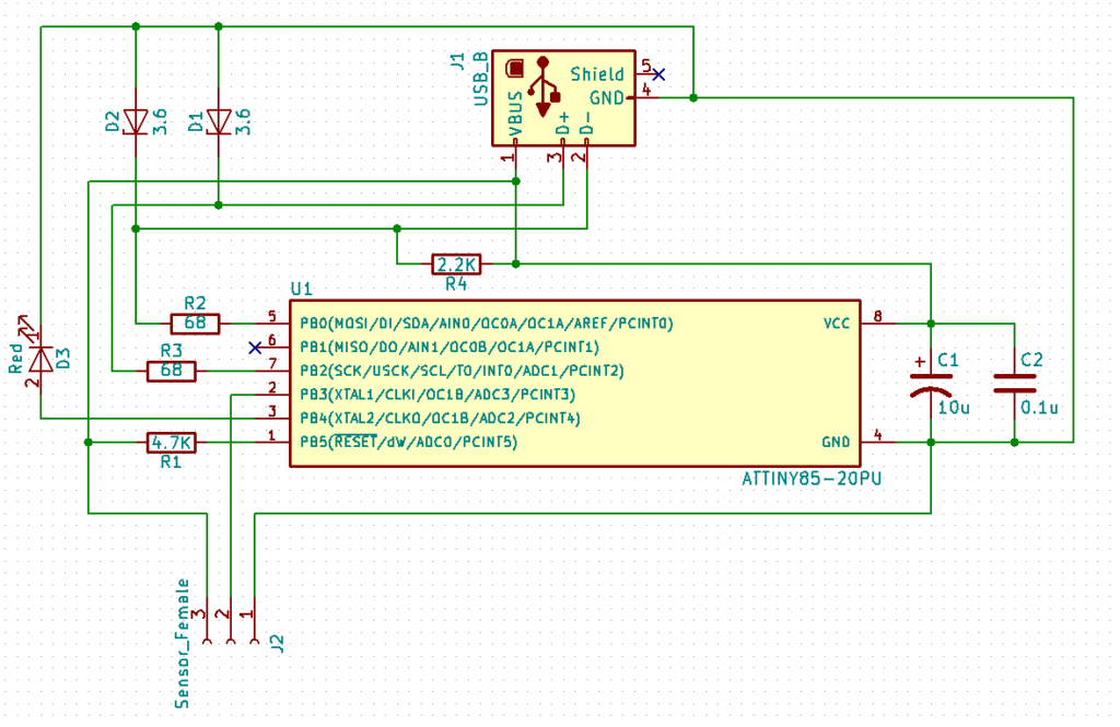
A red LED is used to signal the operation status, and two Zener diodes are used to drop the 5V supply voltage down to 3.6 volts for the USB signal lines. Two capacitors are used to smooth out the power supply, but I think they are not strictly necessary.
Next, I printed, etched and assembled the circuit. After debugging a few problems related to my own stupidity, the PCB was ready to be programmed.
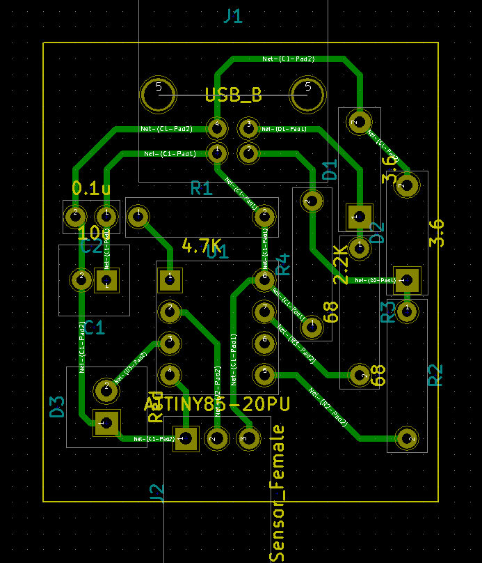
PCB trace layout 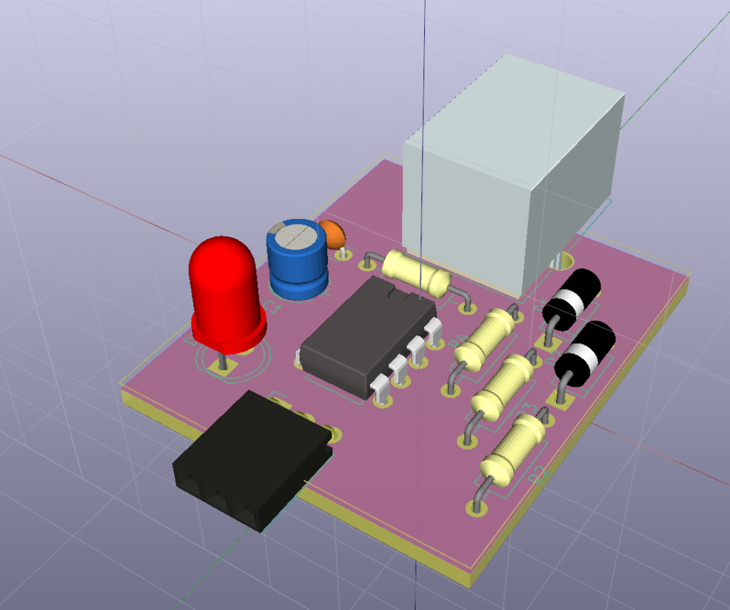
3D render
The Firmware
Programming the ATtiny is pretty easy, I use the avrdude software and an USBasp ISP adapter.
The firmware code relies heavily on the excellent V-USB library by Objective Development. This library implements USB V1 completely in software, as this microcontroller has no native USB interface.
Apart from handling the USB stuff, the code is pretty simple: Initialize the ADC, blink the LED, and then in a loop query the ADC, pack the value into a USB packet and send it off.
int main(void)
{
    uchar calibrationValue = eeprom_read_byte(0); // calibration value from last time
    if (calibrationValue != 0xff) OSCCAL = calibrationValue;
    usbDeviceDisconnect();
    uchar i;
    for (i = 0; i < 20; i++) _delay_ms(15); // 300 ms disconnect
    usbDeviceConnect();
    DDRB |= 1 << PB4;
    adcInit();
    usbInit();
    sei();
    PORTB |= 1 << PB4;
    for (;;)
    {
        adcPoll();
        usbPoll();
        if (usbInterruptIsReady()) usbSetInterrupt(reportBuffer, sizeof(reportBuffer));
    }
    return 0;
}
A small but really interesting hack is provided by the library: Because the internal oscillator of the Attiny is not precise enough for USB timing, the code measures the signal times of the USB packets received from the computer, and detunes the internal oscillator accordingly using the OSCCAL register.
The Software
The firmware presents itself as a HID-compliant game controller to any OS supporting the HID protocol (in my case Windows), such that no device driver is needed.
However, some games do not support multiple controllers at the same time. For these games I adapted a small software tool based on VJoy, which merges multiple controller inputs into one virtual controller.
Sources and Downloads
The hardware and firmware can be found on my GitHub repository at https://github.com/StarGate01/Handbrake/.
The small VJoy tool I forked from https://github.com/shaise/JoystickMerger into https://github.com/StarGate01/JoystickMerger.
Very nice indeed!